


Page 8
Heat & Glo • NorthStar EPA Fireplace • 480-1081C
September 1, 2008
September 1, 2008
September 1, 2008
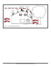
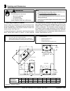
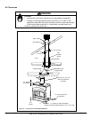
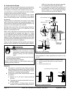
Figure 8.1 Typical Fireplace System
Note: Junction box should be installed during initial setup
NOTE: Illustrationsused throughouttheseinstructions
reect“typicalinstallations”andarefordesignpurposes
only. Actual installation may vary slightly due to individual
design preferences. However, minimum clearances must
be maintained at all times.
The illustrations and diagrams used throughout these instal-
lation instructions are not drawn to scale.
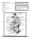
C. Typical Fireplace System
TheHeat&Gloreplacesystemconsistsofthefollowing:
• Fireplace
• Firebrick
• Chimney termination cap
• Chimney system
• Hearth extension
• Outsideair
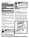
Requiredcomponentsinclude:
• Chimney Air Kit (with SL 300 Series Pipe)
Optionalcomponentsinclude:
• Firescreen
• Lintel Bar
• Heat Zone Kit
• Top Vent Kit
to avoid major reconstruction.
Termination Cap
Chimney penetrates roof
preferably without affecting
roof rafters
Offset/Return
(with hanger straps)
Attic insulation shield
(not shown) must be
used here to keep
insulation away
from chimney if
attic is insulated
Storm Collar
Framing headed
off in ceiling joists
Mantel
Decorative facing
and trim
Protective metal
hearth strip(s)
Hearth extension
Factory-built fireplace
Non-combustible
roof flashing maintains
minimum clearance
around chimney
Additional lateral
support for chimney
above roof (or enclosed
in chase) if needed
Chimney system
Combustible
framing/header
on top of V-shaped
standoffs (spacers)
Enclosed space above
and around fireplace
Support straps
on rafter supports
chimney (not shown)
Outside
combustion air
Outside
combustion air