


September 1, 2008
September 1, 2008
Heat & Glo • NorthStar EPA Fireplace • 480-1081C
Page 33
INSTALLATION
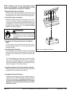
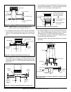
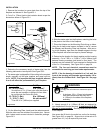
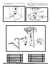
1. Remove the knockout or cover plate from the top of the
replaceanddiscardit.SeeFigure33.1.
2. Cut a 3 in. (76mm) hole in the insulation board as per the
dimensions shown in Figure 33.1.
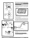
Adapter
Mounting
Plate
Starter Pipe
Knockout
Cut a 3 in. (76mm) ho
le
in insulation board
3-13/16 in.
(97mm)
3-1/8 in. (79mm)
C
L
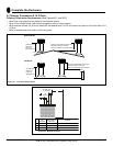
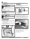
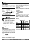
Run Length Cut Pipe
20 - 40 ft (6-12m) 2 in. (51mm)*
*A minimum of 2 in. (51mm) pipe must be used to
cover the raw insulation to prevent it tfrom blow-
ing out through the Return Air Grille.
10 - 20 ft (3 - 6m) 8 in. (203mm)
3 - 10 ft (1 - 3m) No cut needed**
**Use full 16 in. (406mm) as supplied
3. Determine the necessary length of starter pipe from the
following table and cut as required. See Figure 33.2.
4.Thestarterpipeisshippedat.Aftercuttingtotherequired
length, manually roll the pipe together and snap lock into
place. NOTE: It is important the pipe length be adhered
to or it will affect the performance of your replace.
Figure 33.1
Figure 33.2
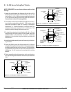
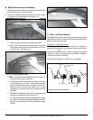
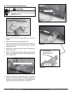
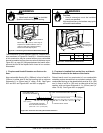
6.Slidethestarterpipeintothereplace,matchingtheholes
intheplatetotheholesinthereplace.
7.PlacetheAdapterontheMountingPlateliningupholes.
Using the 4 sheet metal screws included in the kit, secure
theAdapterandMountingPlateintoreplace.Aftersecur-
ingtothereplace,tapedowntheAdapteredgestothetop
ofthereplacewithaluminumtapetopreventleakage.
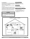
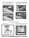
8. Determine the location for the air register and fan housing
assembly.Cuta7-5/8in.x13-5/8in.(143x346mm)hole
betweenframingmembers(wallstudsoroorjoists).The
brackets can be rotated 180° and mounted to the back side
of the 2 x 4 if necessary. See Figure 34.2 on page 34.
NOTE: The fan and electrical connections must be
accessible for servicing per local code requirements.
NOTE: If the fan housing is installed in a 2 x 4 wall, the
front of the housing will protrude approximately 1/4 in.
(6mm) from the nished wall. See Figure 34.1 on page
34.
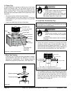
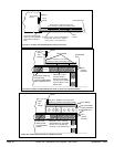
9. Attach enough 6 in. (152mm) B-Vent as required for
your installation to the fan housing. A maximum of (4) 90°
elbows is recommended. Securely twist lock the B-Vent
to the Adapter.
Also screw the B-Vent to the outlet box on the fan housing.
See Figure 34.2 on page 34.
Support duct at intervals of no
greater than 4 ft (1 m) as required by local code.
Figure 33.3
Fire Risk
Comply with all minimum clearances speci-
ed.
• Aminimum1/2in.(13mm)airclearance
must be maintained at the back and 1
in.(25mm)tothesidesofthereplace
assembly.
WARNING
5.OntheMountingPlate,handbendthetabsdownward.
Slide the tabs over the outside of the starter pipe. Secure
with 4 sheet metal screws included in fasteners package.
Figure 33.3.