


8
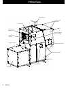
PF100
Mounting Screws
Fig. 11
Fig. 13
Fig. 14
Fig. 12
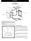
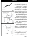
Blower Assembly
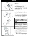
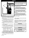
Install the blower mounting brackets on the blower
as shown in Fig. 11.
1. Install ( 4) Tek screws on each side where shown
in Fig. 11. Start with the two center screws.
NOTE: There are two small holes in the discharge
end of the blower that match the two center holes on the
small angle of the blower bracket. The two (2) outer
holes are drilled by theTek screws.
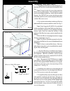
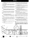
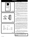
2. Mount blower with brackets installed on the
furnace as shown in Fig. 12. Each side will require 6
Tek screws.
NOTE: The furnace blower opening is made large
enough for the use of a 1500 or 2000 CFM blower.
The blower mounting brackets will fit either blower. The
inner hole pattern is for the 1000 CFM blower and the
outer pattern is for the 1500 or 2000 CFM blower.
NOTE: These Blower Motors are not designed to
be operated without any positive static back
pressure. OPERATION WITHOUT SUPPLY
DUCTWORK OR IN FREE AIR WILL CAUSE
MOTOR OVERLOAD AND PREMATURE
FAILURE.
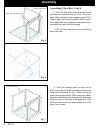
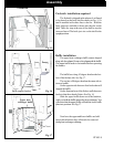
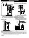
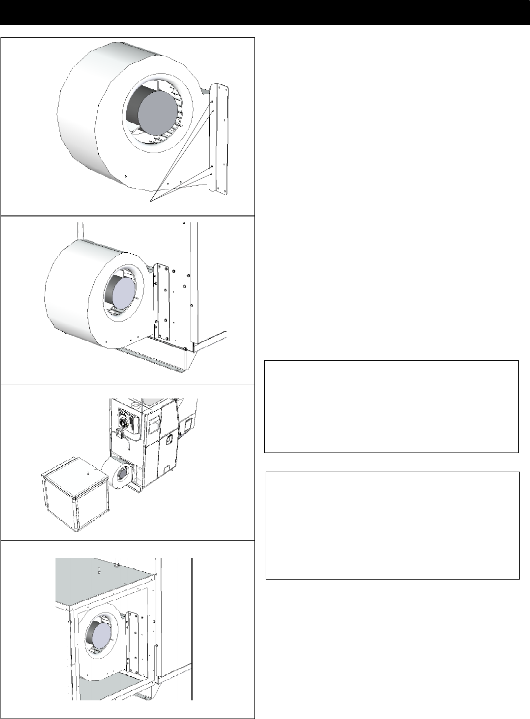
3. Mount the filter box on the furnace with ( 8 )
10 x 3/4 Tek screws, 3 on each side. Visually locate
these holes so you are familiar with their location on the
filter box and the furnace. Access to the mounting holes
can be gained through the blower access panel cover
and the filter opening. See Fig. 14.
Note: Two pieces of 2x4 stacked laying flat on
the floor 12 inches from the blower opening will support
the filter box during installation.
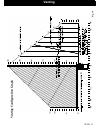
CAUTION: Regardless of the supply air duct size
installed, the Distribution Blower Motor MUST be
checked for running Amperage. Check the motor name
plate for the full load AMPS. If the amperage is running
higher than that listed, a supply air restricting damper
may be required to increase the supply plenum positive
static pressure.
Assembly