


4
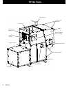
PF100
Venting
Use 4” pellet vent pipe to vent your PF 100.
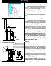
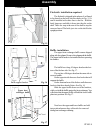
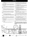
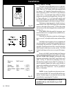
A combustion blower is used to extract the com-
bustion gases from the firebox. This creates a negative
pressure in the firebox and a positive pressure in the
venting system as shown in fig. 2. The longer the vent
pipe and more elbows used in the system, the greater
the flow resistance. Because of these facts we recom-
mend using as few elbows as possible and 30 feet or
less of vent pipe. The maximum horizontal run should
not exceed 18 feet.
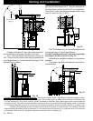
Be sure to use wall and ceiling pass through
fittings (which are approved for pellet vent pipe )
when going through combustible materials. Be sure
to use a starting collar to attach the venting system to the
stove. The starting collar must be sealed to the
stove flue collar with high temp silicone caulking
or aluminum tape, and screwed into the stove flue
collar at least three (3) places.
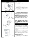
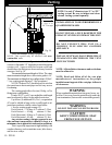
Vent Pipe
4” pellet venting pipe ( also known as PL vent ) is
constructed of two layers with air space between the
layers. This air space acts as an insulator and reduces
the outside surface temperature to allow a clearance to
combustibles of only 2 inches. This 2 inch clearance is
also approved by the pipe manufacturers. See images
on left. See page 14 (Fig. 24 and 26) for larger images.
The sections of pipe lock together to form an air
tight seal in most cases; however, in some cases a per-
fect seal is not achieved. For this reason and the fact
that the PF100 operates with a positive vent pressure,
we specify that all joints within the structure should
also be sealed with clear silicone.
Fig. 1
Fig. 2
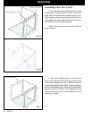
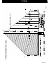
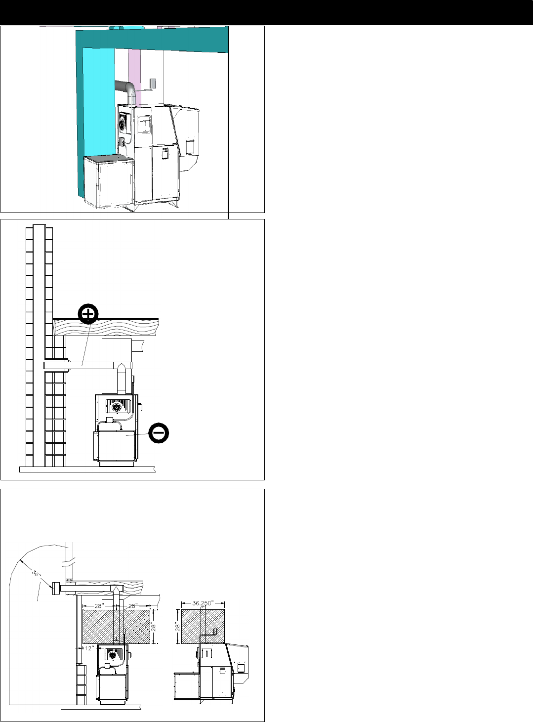
Clearances and Venting
The shaded areas are the clear-
ances for the PL vent pipe that must
be maintained at 3”. After the vent-
ing leaves the shaded area it may be
installed at 2” to combustibles.
(Only UL listed wall pass-throughs
and fire stops must be used.)
See NOTES:
on page 12
NOTE:Use only 4” diameter type “L” or “PL”
venting system. Be sure to inspect and clean
exhaust venting system frequently.
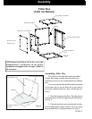
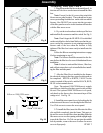
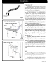
The first thing that needs to be done is deciding
where and how the furnace will be installed.
Things that need to be taken into consideration are
VENTING, SUPPLY& RETURN DUCTING, ELEC-
TRICAL, and Condensation drainage (if A/C is in-
stalled). Don’t forget access to the furnace for service.
When the return air inlet position is known the filter
box and distribution blower can be installed. See pages
5, 6, 7, 8.
When the furnace is set into place venting can be
done.
Design
Assembly