


20
PF100
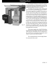
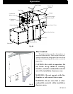
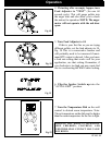
Installing Electrical Power:
To install power to the furnace first remove the cover
on the circuit breaker junction box shown.
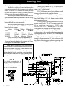
Inside you will find the main terminal block.(See wir-
ing diagram on page 36 for location of main terminal block
and proper power connections). In the bottom of the box a
knockout hole is provided for the incoming wire.
The minimum recommended circuit is 15 Amp 120
V.A.C. 60 Hz. This furnace should be the only appliance
on the circuit.
This furnace should never be powered by the use
of an extension cord.
The recommended high and low voltages are, 130
V.A.C. 60 Hz maximum high voltage, and 113 V.A.C. 60
Hz minimum low voltage.
The furnace will continue to operate at voltages as
low as 105 V.A.C. , although it can not be guaranteed that
automatic ignition will occur. Also there is the possibility of
a distribution blower motor overload.
NOTE: If other sources of electrical power are
to be used ( such as a generator ) for normal opera-
tion or emergency operation, this source should be
checked before installation. Many generators and
inverters may not supply 120V.A.C. 60Hz. power
stable enough to operate the control board properly.
(Control board damage could occur). Checking & Re-
cording the Low Draft:
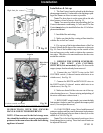
Fig. 37
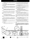
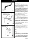
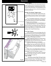
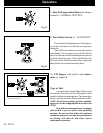
After the venting is completed, the firebox low draft
will need to be checked and possibly adjusted. After re-
moving the 3/8” bolt from the draft hole shown in Fig. 38,
insert the draft meter tube. The inner ash door and the
hopper lid must be latched during this test. ( It is recom-
mended that the draft meter have a scale of 0 to 1” WC.)
Turn the Furnace Control to “Test”. this will start the
combustion blower and allow you to check and record the
High Draft ______ - IWC date _______ (There is no
adjustment for the High Draft)
After the first 60 seconds the “Test” mode lowers the
combustion blower voltage to the Low Burn voltage. (The
“Test” mode cycles the voltage from high to low every 60
seconds).During this lowered voltage cycle the Low Burn
Draft must be checked and adjusted if necessary. The
recommended low draft setting should be between -.25 &
-.35 IWC. Depending on the amount of vertical rise, it may
not be possible to get a low draft reading in this range. In
this case, a maximum low draft of -.55 is acceptable.
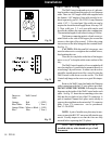
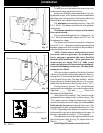
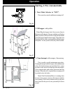
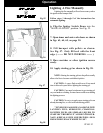
The adjustment screw is through the small hole to the
right of the Igniter Light. See Fig. 39. Adjusted the Low
Draft to __________ -IWC.
Don’t forget to turn the control back to #4.
Installation
Draft meter bolt
Furnace Control
Fig. 38
Low Draft Adjustment Pot
“Test”
Fig.39