


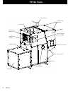


7PF100
Fig. 8
Fig. 9
Fig. 10
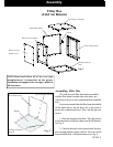
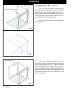
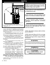
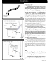
5. Place the top on the filter box as shown in figure 8. At
this time all Tek screws can be inserted around the filter
box.
Top
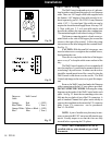
Access Panel
Cover opening
3 Speed Switch
Note: Except for the (6) screws that attach the
blower access panel in place. There should not be any
screws protruding from the box on the side toward the
furnace. Also DO NOT put a screw into the top center
of the filter panel as a screw in this location will interfere
with the filter access cover.
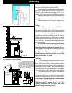
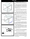
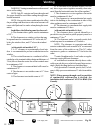
6. Pry out the two knockouts in the top of the box
and install the flex connector and the switch. See Fig. 9.
Note: Don’t forget the HI-MED-LO switch label
on the switch before the locknut.Make sure that the set-
screw on the flex connector is not pointing toward the
furnace end of the box when the locknut is fully
tightened.The filter box is now ready to install onto the
furnace.
Follow the Blower mounting instructions on page
8 before continuing to step #7.
Note: The blower should be mounted on the fur-
nace before the filter box for ease of distribution blower
installation.
Note: It is best to wait until the blower , filter box,
and cold air return duct work is installed before install-
ing the filter and side panel.
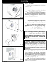
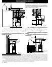
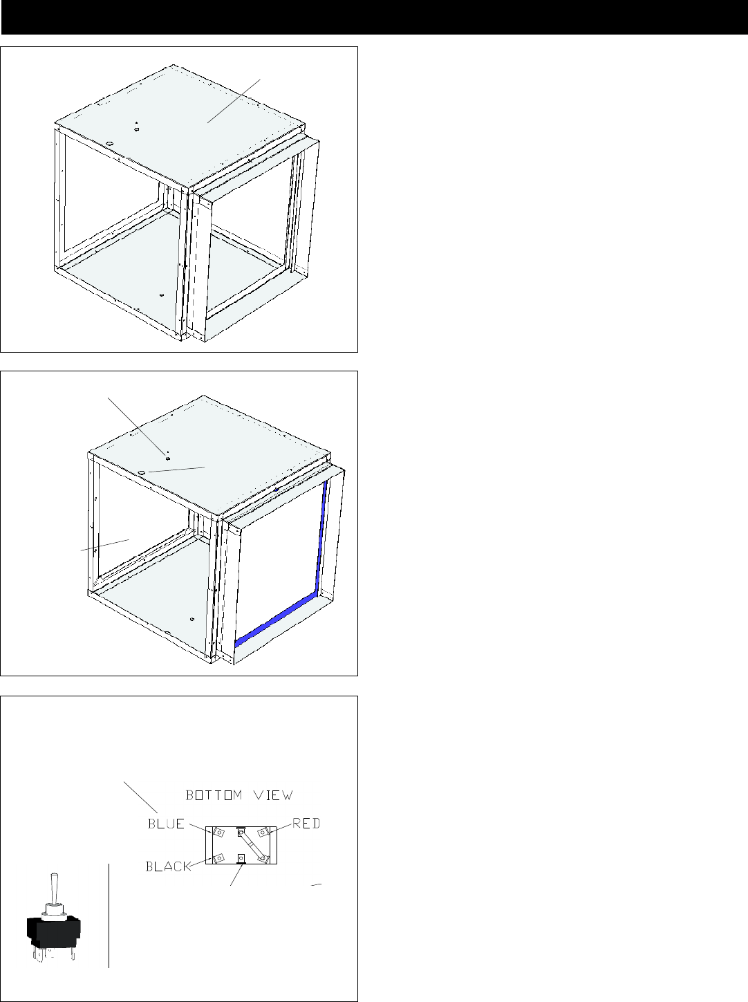
7. After the Filter Box is installed on the furnace
the electrical wiring to the three speed switch needs to
be completed. WHITE to WHITE, VIOLET to the
center terminal of the switch, and the BLACK, RED,
BLUE to the terminals shown.
Note: The optional 1500 CFM blower is a single
speed blower, therefore the three speed switch will not
be used. The optional 2000CFM blower is a 4 speed,
only hook up the three colors shown and tape off the
orange wire. See Fig. 10.
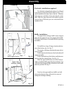
8. Install the access panel cover by hooking the lip
at the bottom of the cover over the edge in the filter box.
Use 6 Tek screws to secure the access panel.
9. To install the filter, insert the filter into the filter
slot and slide completely into the frame. Take note to
the air flow arrow on the filter when installing.Slide the
filter access cover over the opening with the upright angle
toward the filter box. If a Tek was put into the middle
hole by mistake, remove the screw to allow the access
cover to fit properly.
Assembling Filter Box, Cont’d
Violet 120VAC
Yellow on 2000 CFM motor
Flex connector
Assembly