


10
PF100
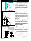
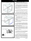
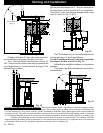
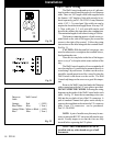
The minimum vent configuration is a 90
o
or Tee on
a starter collar and a 24” length horizontal through an
exterior wall. A cap or other bird screen on the end
should direct the flue gasses down and away from the
structure. See Fig. 18.
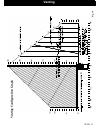
The maximum horizontal length is 18 feet. The mini-
mum termination height above the exterior grade is 18”.
The maximum total length of any configuration is 30 feet*.
* ( see venting graph on page 13 for exceptions )
NOTE: Cleanout Tee’s should always be used on
the transitions to horizontal pipe to allow easy access
for cleaning.
The venting gragh allows for (one) 90 deg. or Tee
fitting in any configuration.
If more 90’s, T’s, or 45’s are needed the total length
must be adjusted to allow for the added restriction.
Up to four (4) additional 90’s, Tee’s, or equivalent
45’s can be added as long as the overall length is ad-
justed in accordance with the values listed below.
( See the venting graph on page 12.)
Each Vertical ---- 90 deg. or T subtract 2.5 feet
Each Vertical ---- 45 deg. subtract 1.5 feet
Each Horizontal - 90 deg. or T subtract 5.0 feet
Each Horizontal - 45 deg. subtract 2.5 feet
Any exterior venting (vent pipe exposed to out-
side ambiant temperatures) should be kept to a
minimum, due to potential condensation problems.
This is especially important in high humidity cold
weather climates, such as maritime areas, lake shores,
and low river valleys.
4” Type “L” or
“PL” Vent pipe
This is the minimum venting configuration.
NOTE: This would only be allowed with non-
combustible walls.
Fig. 18
Venting
NOTE: All installation clearnaces and restrictions
must be adhered to.
NOTE: Read and follow all of the vent pipe
manufacturers’ instructions on the proper
installation and support of the vent pipe. Adhere to
all clearances.
Keep combustible materials such as grass, leaves, etc.
at least 3 feet away from the point directly under the
vent termination. (between the vent and the ground)
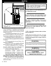
WARNING
KEEP COMBUSTIBLES AWAY
FROM FLUE OUTLET.
CAUTION
DO NOT INSTALL IN SLEEPING ROOM
WARNING
DO NOT INSTALL A FLUE DAMPER IN THE
EXHAUST VENTING SYSTEM OF THIS UNIT.
DO NOT CONNECT THIS UNIT TO A
CHIMNEY FLUE SERVING ANOTHER
APPLIANCE.
INSTALL VENT WALL PASS-THROUGHS AT
CLEARANCES SPECIFIED BY THE VENT
MANUFACTURER
INSTALLATION IS TO BE PERFORMED BY A
QUALIFIED INSTALLER.
NOTE: Use only 4” diameter type “L” or “PL”
venting system. Be sure to inspect and clean
exhaust venting system frequently.
Venting