


23
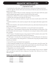
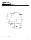
AQUASTAT INSTALLATION
1. Lay the din rail on a at surface with the at side down. Secure one end clamp on the left side.
2. From the right side, slide the A350 control onto the din rail. Slide the control to the left until it is
against the end clamp.
3. Repeat Step 2 with the Y350 power module, connecting it to the A350 control. NOTE: Be careful
when fastening the plug-together connecters located at the top of the controls.
4. Repeat Step 3 with the S-350 control, connecting it to the Y350 power module.
5. Install the other end clamp to the right side of the din rail.
6. Remove the covers on the three controls by using the four screws on each control. (A350, Y350,
S350)
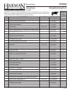
7. Install the terminal box to the controls by using the three chase nipples and locknuts supplied with
the kit.
8. Mount the terminal box with controls to the boiler jacket or any other desired location by the four
holes in the terminal box.
9. Using two 8-32 nuts, install the terminal block over the studs located in the terminal box.
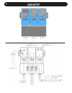
10. A350 Control: 1) Set the jumpers to the heat position. They may already be in this position. 2) Set
the differential to the desired set point. 3) Terminate the wires using the common and the normally
open terminals.
11. Y350 Control: 1) Terminate the power wiring using the 120 VAC terminals on the control. This
will be supplied from the terminal block located in the terminal box.
12. S350 Control: 1) Set the offset to the desired set point. 2) Set the differential to the desired set
point. 3) Set the jumpers to the cooling position. 4) Terminate the wiring using the common and the
normally open terminals.
13. Set the A350 control to the desired water temperature.
14. After locating and installing the sensor well and sensor, wire the sensor to the A350 control. The
terminals marked “sen” and “com” are located in the upper left-hand corner of the A350 control. Make
sure the sensor is inserted into the well fully and secured with a setscrew.
15. Reinstall the covers on the three controls
16. NOTE: Sensor wire can be lengthened up to 50 feet with standard 22 awg t-stat wire. Shielded
cable is generally not required for sensor wiring runs of less than 50 feet. However, if over 50 feet,
follow this guide:
14 awg.....................800 feet
16 awg.....................500 feet
18 awg.....................310 feet
20 awg.....................200 feet
22 awg.....................124 feet