


8 Hampton
®
H35 Direct Vent Freestanding Gas Stove
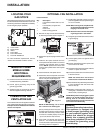
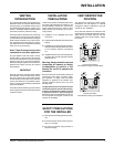
OPTIONAL FAN INSTALLATION
Diagram 1
Diagram 2
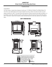
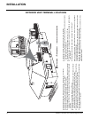
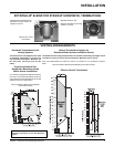
LOCATING YOUR
GAS STOVE
When selecting a location for your stove, ensure
that the clearances listed above are met as well
as ensuring that there is adequate accessibility
for servicing and proper operation.
MANUFACTURED
MOBILE HOME
ADDITIONAL
REQUIREMENTS
1) Ensure that structural members are not cut
or weakened during installation.
2) Ensure proper grounding using the #8
ground lug provided.
3) Appliance must be anchored to the fl oor
with the supplied anchoring methods.
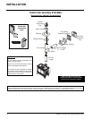
COMBUSTION AND
VENTILATION AIR
The combustion air from this appliance is drawn
from outside the building through the outer fl ue.
Extra provision for combustion air inside the
room is not required.
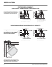
A) Cross Corner
B) Room Divider
C) Island
D) Flat on Wall
E) Flat on Wall Corner
F) Flush with Wall/Alcove
For Vent Termination requirements, see the
"Exterior Vent Terminal Locations" section.
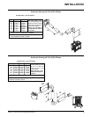
Fan Kit Contains:
Qty. Description
1 Fan Speed Controller with nut, and
knob.
1 Fan Assembly c/w green wire
attached
1 Power cord
1 Plastic locking grommet
1) Remove the Top Control Panel Assembly
by removing the three screws. Diagram 1.
2) Remove the nylon hole plug from the control
panel.
3) Install the fan speed controller onto the
control panel and secure with nut. Connect
remaining wire harness wires to speed
control. NOTE: Speed control wires must
be in the down position when control panel
is in place.
4) Push black knob onto speed control.
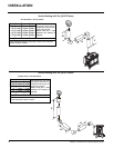
5) Remove the rear access panel on the back
of the stove by removing the 6 screws. Install
the fan onto pins as per Diagram 2.
NOTE: Do NOT damage, cut or remove
the 3" aluminum air intake pipes.
Hint for pushing fan down onto pins - rub a
bit of dish soap on the pins so the grommets
will slide down more easily. Check to make
sure the fan is seated properly on the pins
- try to move the fan back and forth.
6) Push power cord through hole in the rear
panel 14" - 16" and tie a loose knot in the
cord on the inside to prevent the power cord
from being pulled out. Diagram 2.
7) Install locking grommet to power cord and
push through hole in the rear panel and give
a 1/4 turn to secure.
NOTE: When running wires, keep them clear
of valve assembly and tubing to avoid
tangling of wires and valve.
NOTE: Be careful not to cut wires when pass-
ing through holes in the fi rebox.
8) Run green ground wire from fan and connect
to grounding lug.
9) Connect green power cord ground wire to
grounding lug.
10) Run the neutral black wire from power cord
and connect to fan motor.
11) Run the live black wire from power cord and
connect to speed control wire.
12) Connect the white wire of the wire harness
to the fan terminal.
NOTE: Pull excess wire next to fan to
avoid excessive heat from the fi rebox.
13) Ensure all wires are pulled away from fi rebox
to avoid excessive heat and secure with
stick-on wire clip.
14) Re-attach control panel with 3 screws, re-
versing step 1. Re-attach rear access panel
with 6 screws, reversing step 5.
NOTE: When power cord is plugged in, speed
control is in the ON position and stove is
burning, allow 10 - 15 minutes for the ther-
modisc (temperature switch) to activate and
turn on the Fan automatically.
WARNING:
Electrical Grounding Instructions
This appliance is equipped with
a three pronged (grounding) plug
for your protection against shock
hazard and should be plugged
directly into a properly grounded
three-prong receptacle. Do not cut
or remove the grounding prong
from this plug.
INSTALLATION