


32 Hampton
®
H35 Direct Vent Freestanding Gas Stove
LOG SET
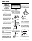
INSTALLATION
Read the instructions below carefully and
refer to the diagrams. If logs are broken
do not use the unit until they are replaced.
Broken logs can interfere with the pilot
operation.
The gas log kit contains the following:
a) 02-43 Rear Log
b) 02-56 Middle Left Log
c) 02-44 Front Left Log
d) 02-46 Left Top Log
e) 02-45 Front Right Log
f) 02-47 Center Log
g) 02-48 Middle Right Log
h) Embers
i) Lava
The "02" refer numbers (i.e. 02-43) are
molded into the rear of each log.
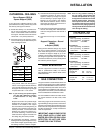
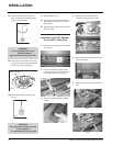
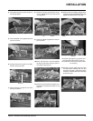
1) Carefully remove the logs from the box and
unwrap them. The logs are fragile, handle
with care - do not force into position.
2) Lift off the Cast Top and remove the glass
front (refer to the "Glass Replacement"
section in this manual).
3) Sprinkle the embers on the left and right
sides of the fi rebox base.
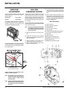
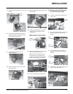
A) 02-43 D) 02-46
G) 02-48
C) 02-44 B) 02-56
F) 02-47
E) 02-45
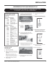
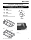
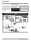
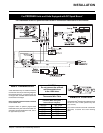
10) Adjust Vent restrictor setting: To set the
Vent restriction as indicated in the diagram,
simply loosen the screws and push the vent
restrictor plate to the correct position. Tighten
the screws.
Vent Restrictor setting at Low Btu
for Straight Horizontal Venting
11) Attach the label "This unit has been con-
verted to..." on top of the Serial # decal over
the higher Btu information.
12) Check for gas leaks.
13) Check inlet and outlet pressures.
14) Check operation of fl ame control. Check
for proper fl ame appearance and glow on
logs.
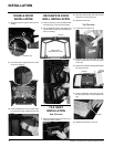
OPTIONAL
BRICK PANEL
INSTALLATION
Unit Btu/h Restrictor Opening
H35 NG 30,000 A 1-3/4" (45mm)
H35 LP 28,500 A 1-3/4" (45mm)
1) Remove the cast top and glass front (see
Glass Replacement section in this manual
for instructions).
2) Remove the log set if installed.
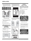
3) Insert the back brick panel fi rst by carefully
slipping it between the back wall of the
fi rebox and the rear log bracket.
Back Panel
Diagram 1
4) Before installing the side brick panels, loosen
the screws for the brick tabs enough so that
you can slide the brick tabs on to the screws
easily but that the tabs are secure. For the
location of the side brick tab screws see
Diagram 1.
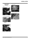
Brick
tab screw
Back
brick
panel
Side
brick
panel
Diagram 2
5) Put the side panels in next. Slide them in
from the front and push them fl at up against
the wall. Be very careful not to scratch them
on the fi rebox hardware.
Left
Side
Panel
Right
Side
Panel
Brick Tab
Screw
Brick
Tab
6) Install the brick tabs (refer to Diagram 2).
Embers Embers