


Hampton
®
H35 Direct Vent Freestanding Gas Stove
21
Diagram 2a
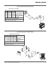
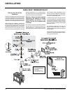
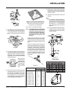
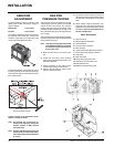
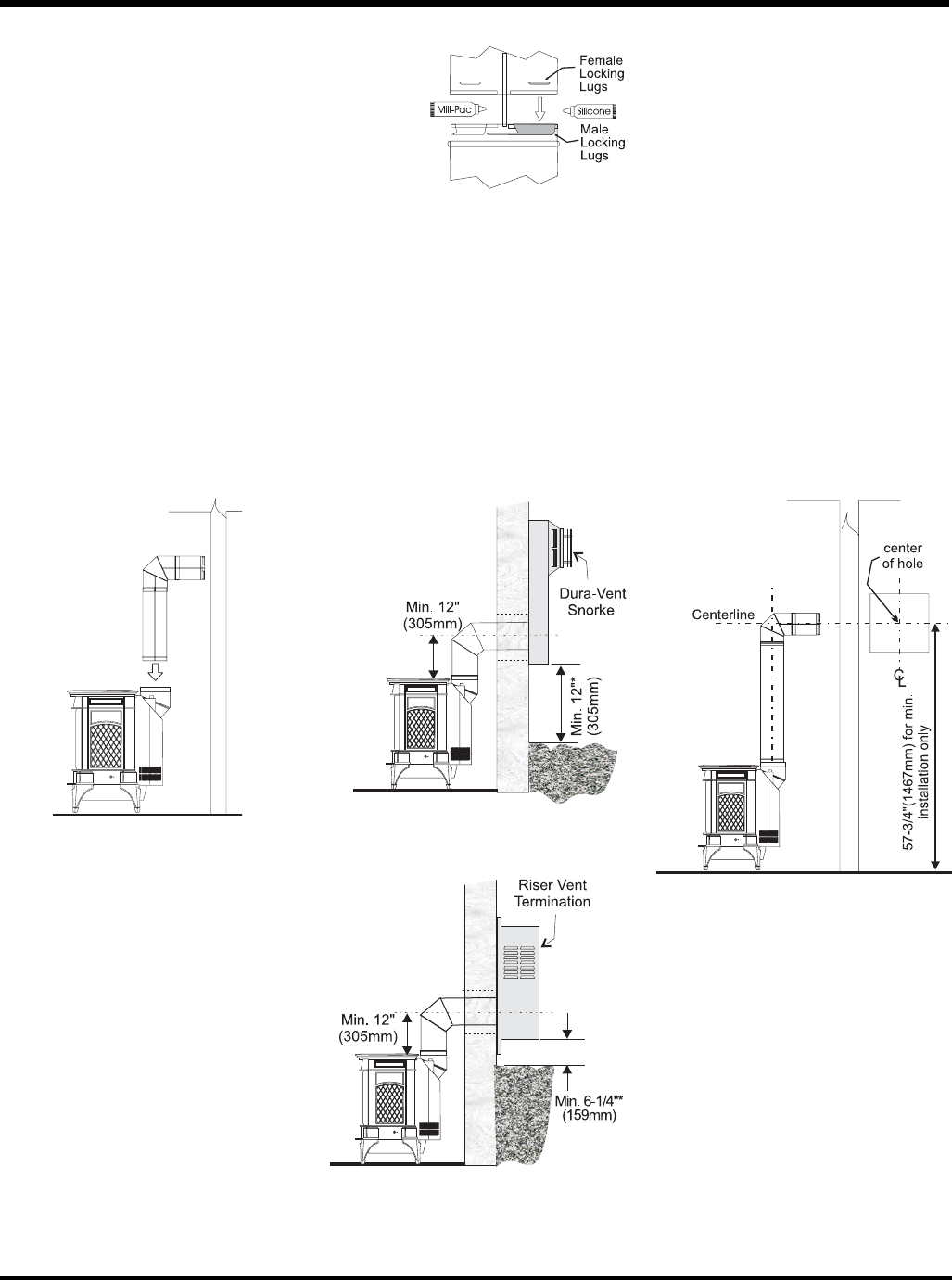
Diagram 3
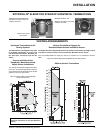
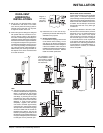
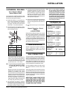
Below Grade Snorkel Installation
If the Snorkel Termination must be installed
below grade, i.e. basement application,
proper drainage must be provided to prevent
water from entering the Snorkel Termination.
Refer to Dura-Vent Installation instructions
for details. Do not attempt to enclose the
Snorkel within the wall, or any other type
of enclosure.
3) With the pipe attached to the stove, slide
the stove into its correct location, and mark
the wall for a 10" x 10" (inside dimensions)
square hole. The center of the square
hole should line up with the centerline of
the horizontal pipe, as shown in diagram
3. Cut and frame the 10 inch square hole
in the exterior wall where the vent will be
terminated. If the wall being penetrated is
constructed of non-combustible material, i.e.
masonry block or concrete, a 7" diameter
hole is acceptable.
*As specifi ed in CGA
B149 Installation Code.
Local codes or regula-
tions may require differ-
ent clearances.
Diagram 2
INSTALLATION
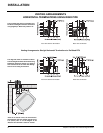
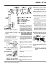
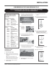
Diagram 1:
Hint: Apply
silicone to
female end.
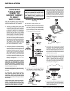
DURA-VENT
HORIZONTAL
INSTALLATIONS
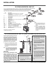
1) Set the unit in its desired location. Check
to determine if wall studs or roof rafters
are in the way when the venting system is
attached. If this is the case, you may want
to adjust the location of the unit.
2) Direct Vent pipe and fi ttings are designed
with special twist-lock connections to con-
nect the venting system to the appliance
fl ue outlet. A twist-lock appliance adapter is
installed on the unit at the factory. Assemble
the desired combination of pipe and elbows
to the appliance adapter with pipe seams
oriented towards the wall or ceiling, as much
out of view as possible. The fi nal position-
ing of the pipe and 90
o
elbow assembly is
determined by the mounting orientation of
the adapter on the stove and twist-locked
for a solid connection.
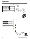
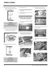
b) Horizontal runs of vent must be sup-
ported every three feet. Wall straps are
available for this purpose.
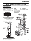
c) Snorkel Terminations:
For installations requiring a vertical rise
on the exterior of the building, 14-inch
and 36-inch tall Snorkel Terminations
and the Riser Vent as shown in Diagrams
2 & 2a are available. Follow the same
installation procedures as used for stand-
ard Horizontal Termination. NEVER
install the snorkel upside down.
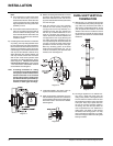
Note:
a) Twist-lock procedure: Four indentations,
located on the female ends of pipes and
fi ttings, are designed to slide straight
onto the male ends of adjacent pipes
and fi ttings, by orienting the four pipe
indentations so they match and slide in
to the four entry slots on the male ends
(Diagram 1). Push the pipe sections
completely together, then twist-lock
one section clockwise approximately
one-quarter turn, until the two sections
are fully locked. The female locking lugs
will not be visible from the outside on
the Black Pipe or fi ttings. They may be
located by examining the inside of the
female ends. Apply sealant "Mill-Pac" to
inner pipe and high temp silicone sealant
to outer pipe on every twist-lock joint.