


Hampton
®
H35 Direct Vent Freestanding Gas Stove
23
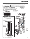
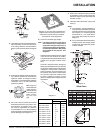
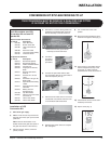
Roof Pitch Minimum Vent Height
Feet Meters
fl at to 7/12 2 0.61
over 7/12 to 8/12 2 0.61
over 8/12 to 9/12 2 0.61
over 9/12 to 10/12 2.5 0.76
over 10/12 to 11/12 3.25 0.99
over 11/12 to 12/12 4 1.22
over 12/12 to 14/12 5 1.52
over 14/12 to 16/12 6 1.83
over 16/12 to 18/12 7 2.13
over 18/12 to 20/12 7.5 2.29
over 20/12 to 21/12 8 2.44
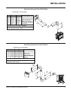
Offset Chart
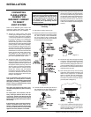
Diagram 12
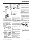
7) Ensure vent is vertical and secure the base
of the fl ashing to the roof with roofi ng rails,
slide storm collar over the pipe section and
seal with a mastic.
8) Install the vertical termination cap by twist
locking it.
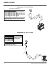
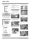
Notes:
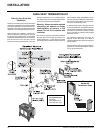
a) For multistorey vertical installations, a
Ceiling Fire stop (Part # 963) is required
at the second fl oor, and any subsequent
fl oor. Diagram 12. The opening should
be framed to 10 " x 10" inside dimen-
sions, in the same manner as shown in
Diagram 9.
b) Any occupied areas above the fi rst fl oor,
including closets and storage spaces,
through which the vertical vent passes,
must be enclosed.
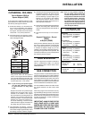
Diagram 11
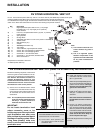
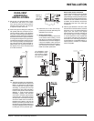
Diagram 9
Diagram 8
3) To install the Round Support Box/Wall Thim-
ble in a fl at ceiling, cut a 10 inch square hole
in the ceiling centred on the hole drilled in
Step 2. Frame the hole as shown in Diagram
9.
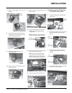
Hint: Apply the
sealant (Mill-Pac
and/or high tem-
perature silicone)
to the outer pipe
before connect-
ing the inner
pipe.
INSTALLATION
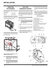
4) Assemble the desired lengths of black pipe
and elbows necessary to reach from the
appliance adapter up though the Round
Support Box. Insure that all pipes and elbow
connections are in the fully twist-locked
position and sealed.
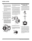
Diagram 10: The upper half of the fl ashing is
installed under the roofi ng material and not
nailed down until the chimney is installed.
This allows for small adjustments.
6) Continue to assemble pipe lengths.
Note: If an offset is necessary in the attic to
avoid obstructions, it is important to
support the vent pipe every 3 feet, to
avoid excessive stress on the elbows,
and possible separation. Wall straps
are available for this purpose. See
Diagram 5.
Galvanized pipe and elbows may be utilized
in the attic as well as above the roofl ine.
The galvanized fi nish is desirable above the
roofl ine due to its higher corrosion resist-
ance.
Continue to add pipe sections through the
fl ashing until the height of the vent cap meets
the minimum height requirements specifi ed
in Diagram 11 or local codes. Note that for
steep roof pitches, the vertical height must
be increased. A poor draft, or down drafting
can result from high wind conditions near
big trees or adjoining roof lines, in these
cases, increasing the vent height may solve
the problem.
5) Cut a hole in the roof centred on the small
drilled hole placed in the roof in Step 2. The
hole should be of suffi cient size to meet
the minimum requirements for clearance
to combustibles of 1-1/4". Slip the fl ashing
under the shingles (shingles should overlap
half the fl ashing) as per Diagram 10.