


22 Hampton
®
H35 Direct Vent Freestanding Gas Stove
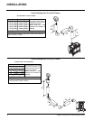
Diagram 7
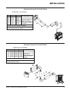
Diagram 6
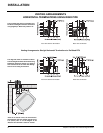
Diagram 5
Diagram 4
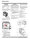
b) The location of the horizontal vent termi-
nation on an exterior wall must meet all
local and national building codes, and
must not be blocked or obstructed. See
diagram in the "External Vent Terminal
Locations" section.
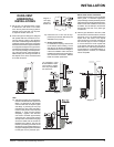
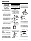
4) If installing the vent termination to a wall with
vinyl siding, the Vinyl Siding Standoff must
be used. Attach the Vinyl Siding Standoff to
the Horizontal Vent Termination, but fi rst run
a bead of non-hardening mastic around its
outside edges, so as to make a seal between
vent cap and the standoff. Install the Vinyl
Siding Standoff (Part # 950) between the
vent cap and the exterior wall and attach
with the four wood screws provided. Seal
around the Vinyl Siding Standoff on all four
sides. Diagram 6. The arrow on the vent
cap should be pointing up. Insure that the
1-1/4" clearances to combustible materials
are maintained. See diagram 4.
Note: If installing termination on a siding
covered wall, a vinyl siding standoff or
furring strips must be used to ensure
that the termination is not recessed
into the siding. The four wood screws
provided should be replaced with ap-
propriate fasteners for stucco, brick,
concrete, or other types of sidings.
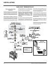
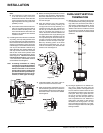
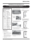
5) Before connecting the horizontal run of vent
pipe to the vent termination, slide the black
decorative wall thimble cover over the vent
pipe, then slide the Wall Thimble (Part # 942)
over the vent pipe.
6) Slide the appliance and vent assembly
towards the wall carefully inserting the
vent pipe into the vent cap assembly. It is
important that the vent pipe extends into
the vent cap a suffi cient distance so as to
result in a minimum pipe overlap of 1-1/4
inches. Secure the connection between the
vent pipe and the vent cap by attaching the
two sheet metal strips extending from the
vent cap assembly into the outer wall of the
vent pipe. Use the two sheet metal screws
provided to connect the strips to the pipe.
Bend any remaining portion of the sheet
metal strip back towards the vent cap, so
it will be concealed by the decorative wall
thimble cover. See Diagram 5.
DURA-VENT VERTICAL
TERMINATION
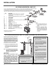
1) Maintain the 1-1/4" clearances (air spaces)
to combustibles when passing through ceil-
ings, walls, roofs, enclosures, attic rafter, or
other nearby combustible surfaces. Do not
pack air spaces with insulation. Check the
"Exterior Vent Terminal Locations" section
for the maximum vertical rise of the venting
system and the maximum horizontal offset
limitations.
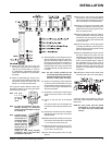
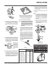
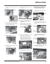
2) Set the gas appliance in its desired loca-
tion. Drop a plumb bob down from the
ceiling to the position of the appliance fl ue
exit, and mark the location where the vent
will penetrate the ceiling. Drill a small hole
at his point. Next, drop a plumb bob from
the roof to the hole previously drilled in
the ceiling, and mark the spot where the
vent will penetrate the roof. Determine if
ceiling joists, roof rafters or other framing
will obstruct the venting system. You may
wish to relocate the appliance or to offset,
as shown in Diagram 8 to avoid cutting load
bearing members.
Note:
a) The horizontal run of vent should have
a 1/4 inch rise for every 1 foot of run
towards the termination. Never allow the
vent to run downward. This could cause
high temperatures and may present the
possibility of a fi re.
INSTALLATION
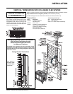
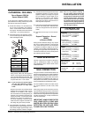
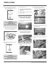
7) Install wall thimble in the center of the 10"
square and attach with wood screws.
8) Slide the decorative wall thimble up to the
wall surface being careful not to scratch the
paint and attach with screws provided. Apply
decorative brass or chrome trim if desired.
See Diagram 6.