


Hampton
®
H35 Direct Vent Freestanding Gas Stove
25
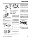
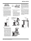
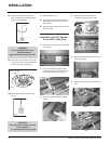
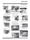
4) Assemble the desired lengths of Black Pipe
and Elbows necessary to reach from the
appliance adapter up through the support
box and fl ashing to proper height as per
Diagram 12, local codes or the "Exterior
Vent Terminal Locations" section. Ensure
that all pipe and elbow connections are in
their fully twist lock position.
5) Ensure vent is vertical and secure fl ashing to
the roof with roofi ng nails. Slide the storm
collar over the pipe section and seal with a
mastic.
6) Twist lock the vent cap on to the last sec-
tion.
Support Extensions - Round
(RDSE)
or Square (SQSE)
Steep pitched cathedral ceilings may require
the use of a support extension. This piece fi ts
down inside the support and can be adjusted
to increase the support's length by up to 22"
(559mm). The extension is attached to the sup-
port using the eight metal screws provided. Be
sure there is at least a 2" (51mm) overlap where
the extension joins the support.
HIGH ELEVATION
This unit is approved in Canada for altitude to
4500 ft. (CAN/CGA-2.17-M91). For Natural
Gas installations above 4500 ft. follow current
CAN/CGA-B149.1.
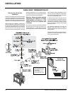
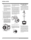
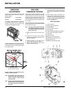
GAS CONNECTION
The gas connection is a 3/8" NPT 90
o
elbow. The
gas line can be rigid pipe or to make installation
easier, use a listed fl exible connector and/or cop-
per tubing if allowed by local codes. Since some
municipalities have additional local codes it is
always best to consult with your local authorities
and the CAN/CGA B149 installation codes.
For USA installations follow local codes and/or
the current National Fuel Gas Code, ANSI
Z223.1.
When using copper or fl ex connectors use only
approved fi ttings. Always provide a union so that
gas lines can be easily disconnected for burner
and/or valve servicing. Flare nuts for copper lines
and fl ex connectors are usually considered to
meet this requirement.
IMPORTANT: ALWAYS CHECK FOR
GAS LEAKS WITH A SOAP AND
WATER SOLUTION OR GAS LEAK
DETECTOR. DO NOT USE OPEN
FLAME FOR LEAK TESTING.
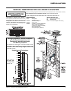
SYSTEM DATA - H35
For 0 to 4500 feet altitude
Natural Gas
Max. Input Rating 36,000 Btu/h
Min. Input Rating 18,000 Btu/h
Orifi ce Size #33 DMS
Convertible to:
Max. Input Rating 30,000 Btu/h
Min. Input Rating 14,300 Btu/h
Orifi ce Size #37 DMS
Propane
Max. Input Rating 34,000 Btu/h
Min. Input Rating 17,500 Btu/h
Orifi ce Size #51 DMS
Convertible to:
Max. Input Rating 28,500 Btu/h
Min. Input Rating 15,000 Btu/h
Orifi ce Size #52 DMS
Supply Pressure
Natural Gas min. 5.0" w.c.
Propane min. 12.0" w.c.
Manifold Pressure
Natural Gas 3.8" +/- 0.2" w.c.
Propane 11" +/- 0.2" w.c.
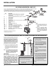
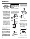
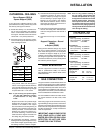
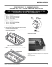
CATHEDRAL CEILINGS
Round Support (RDS) &
Square Support (SQS)
If your home has a cathedral ceiling (no attic
space between the ceiling and the roof), install
the chimney and support as follows.
1) Situate the chimney in a convenient loca-
tion as near as possible to the appliance
outlet. Cut and frame a hole in the roof for
the support. The sides of this hole must be
vertical with 1 1/4" (32mm) clearance.
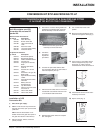
2) Place the support in the opening. Lower it
to the correct height as determined by the
table and diagram below.
Using a level, make sure the support is
vertical. If the support extends above the
roof, cut it fl ush with the top of the roof. Nail
the support to the frame opening using (8)
3" spiral nails or #8 x 1-1/2" screws.
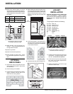
Note: If you are using a 6" square support
you may fi nd it diffi cult to screw it
in place because it is fairly small
inside.
Simpson Dura-Vent has provided angle
brackets with this support which can be
screwed to the outside of the support
box and nailed to surrounding framing as
required. Use a minimum of four #8 x 1/2"
screws per bracket. In some cases these
brackets may need to be trimmed (e.g.:
to fi t under a fl ashing). Place the Finish
Collar around the support and fasten it to
the ceiling using the screws provided.
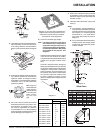
3) Use appropriate roof fl ashing. Place the
fl ashing under the upper shingles and on top
of the lower shingles approximately half of
the fl ashing should be under the shingles.
INSTALLATION
Slope "X"
0/12 - 2/12 4"
2/12 - 7/12 5-1/2"
7/12 - 12/12 6-3/4"
12/12 - 24/12 7-1/2"
24/12+ 12-1/2"
Note: Prior to any pressure testing of
the gas supply piping system that
exceeds test pressures of 1/2 psig,
this appliance must be disconnected
from the piping system. If test pres-
sures equal to or less than 1/2 psig
are used then this appliance must be
isolated from the piping system by
closing its individual manual shut-off
valve during the testing.