


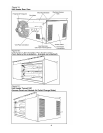
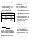
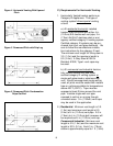
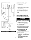
Figure 3B HORIZONTAL THROUGH
vented into a masonry (or concrete) chimney
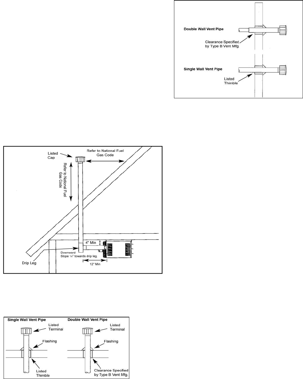
COMBUSTIBLE WALL
lined with material acceptable with recog-
nized standards and the authority having
jurisdiction. Venting into an unlimited masonry
chimney is not allowed. See the National Fuel
Gas Code for common venting.
8. A minimum of 3 corrosion-resistant screws
shall be used to secure vent joints. A listed
vent cap must be utilized to stop drafts and
moisture in the vent.
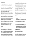
9. Reference the National Fuel Gas Code for
the vertical distance on a pitched roof that
the cap shall extend. See figure 2.
B.) Instructions for Double Wall
(Type B-0) Vent Pipe:
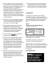
Figure 2 VERTICAL VENTING SLOPED ROOF
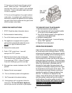
1. Attaching Single Wall Vent Cap to
Double Wall Vent Pipe (Type B-0)
a.) Check for the "Flow" arrow on the vent
pipe. Attach vent pipe to exhaust end of
the double wall pipe.
b.) Slide the cap inside the pipe.
c.) Drill 3 holes through both the pipe and
cap. Use 3/4in. (1.9cm) long sheet metal
screws to secure cap to pipe.
2. Connecting Single Wall Vent Pipe to
Double Wall (Type B-0) Vent Pipe:
a.) Slide single wall pipe into the inner wall
of the double wall pipe.
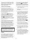
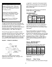
Figure 3A VERTICAL THROUGH COMBUSTIBLE
FLOOR, ROOF
b.) Drill 3 holes through both walls of the
double wall pipe and through single wall
pipe. Using 3/4" (1.9cm) long sheet
metal screws attache the pipes. Do not
over tighten.
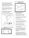
c.) Seal the annular opening by running a
lar
g
e bead of 350˚F
(
175˚C
)
silicone.
The "GAP" between single wall and double
wall pipe shall be sealed. It is not necess-
sary to fill the full volume of the annular area
8