


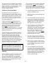
SUSPENSION washers and lock nuts, lock washers and nuts,
or a double nut arrangement similarity used on
Unit(s) must be supported from the structural the unit heater mounting brackets.
part of the building. Do not support from
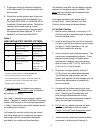
ceiling boards, roof panels or plaster ceiling. This heater also can be installed on a shelf.
The mounting brackets need to be attached
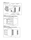
Each unit is provided with two (2) angle as previously indicated. However, for shelf
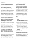
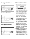
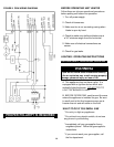
brackets for mounting purposes. See Figure 1A mounting the brackets will have to be secured
on page 5 for typical suspension of the heater. to the bottom of the unit using 1/4" (.6cm)
screws/lag bolts with 1/2". (1.3cm) washers as
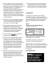
The heater must be installed in a level horizontal overhead joist or truss mounting. Be sure
position so that the heater will operate properly. all clearances to combustible materials are met.
See Figures 1A and 1B on page 5.
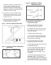
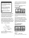
Mounting brackets must be installed first before These unit heaters may also be turned 180 ˚
lifting heater. Decide if the unit is to be installed around from the way they were produced at
as received; that is with the controls on the left the factory. Follow these steps for right side
side when looking at the front of the appliance. in.turned overin. installation (See Figure 1C on
page 5).
Remove and retain the (3) screws along the top
edge of both the front and back of unit. Make 1. Sides become opposite but the front and
sure the screws line up on the mounting back remain in the same relative
brackets with the holes along the front and back position.
top edges. Secure (1) mounting bracket to Bottom panel now becomes the top and
front of the appliance with the retained screw. vice-versa.
Secure the other mounting bracket to the back
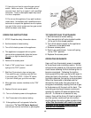
side in the same way that the front one was done. 2. Remove access panel and rotate 180 ˚
reattach it to the unit. This makes sure that
To suspend the heater, fasten the mounting all labels may be read.
brackets to the ceiling joist or truss, using 1/4"
(.6cm) screws/lag bolts with 1/2" (1.3cm) 3. Remove the louvers and springs. Turn
washers. The mounting brackets are slotted to them over so that the air is deflected
accommodate joists on 16 - 24 in. (4.9-7.3m) opposite to what it was originally. Replace
centers. louvers springs. Adjust so that they are
open and positioned to direct heated air
This heater may also be hung using same to the floor.
mounting brackets along with threaded rods.
Attach threaded rod to the heater mounting
COMBUSTION AI
R
brackets, fastening with a top and bottom nut.
Adequate provisions of combustion air must
Next, drill holes into a steel channel or angle iron be provided for this unit heater.
at the same centerline dimensions chosen for
the heater being installed. The steel channels or Since todayft.s buildings and homes are more
angle iron pieces must span and then be tightly built so that less air infiltrates from
fastened to the appropriate structural members. the outside, it is very important that all heating
Cut the rods to the desired length, push through equipment has adequate combustion air.
holes that were made before and secure with
5