


3.
)
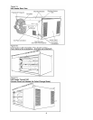
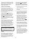
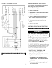
Venting system shall terminate a minimum of 9.) Figure 4 shows how to vent piping through
3 ft.
(
.9m
)
above an
y
forced s
y
stem located a combustible wall with either a thimble or
within 10 ft. (3.1m) and a minimum of 4 ft. (1.2m) type B-0 vent. Check with local authorities
horizontally from, or 1 ft. (.34m) above any having jurisdiction for the proper procedure.
door, window, electric or gas meters,
regulators or gravity air inlet into any building.
The bottom of the vent terminal shall be
located a minimum of 1ft. (.34m) above grade
or above the snow line or whichever is the CLEARANCE
S
greater. The venting system shall terminate
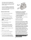
not less than 7ft. (2.1m) above grade adjacent Unit heaters for commercial and industrial
to public walkways. installation shall have a minimum clearance of
7 ft. (2.1m) from bottom of the heater to floor an
d
4.) Horizontal vents shall terminate with a listed residential installation a minimum clearance of
"L" type vent cap. This cap shall maintain a 5 ft. (1.5m) from the bottom of the heater to
12 in. (.3cm) clearance from side of wall. floor.
See Figures 4, 5 and 6 on page 5.
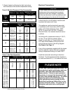
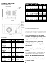
Table 2
5.) If condensation should occur, the venting Clearances to Combustible Material
system shall not terminate over public Based on a 160˚F (70.4˚C)
walkways or over areas where condensation
or vapor will become a nuisance or hazard Top & Bottom: 1 in. (2.54cm)
or detrimental to operation of regulators,
V
ent connector: 4 in. (10.2cm)
relief openings or other equipment.
A
ccess side: 18 in. (45.7cm)
Non-access side: 1 in. (2.54cm)
6.)
This vent system must no
t
be used for the
Rear: 18 in. (45.7cm)
purposes of venting other units.
Make sure that the air intake and discharge
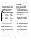
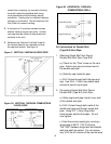
7.) On horizontal venting applications, always air openings are not obstructed.
maintain a 1/4in. (.6cm) per foot (2.54cm)
rise away from the unit. Include a drain Accessibility clearances must take prece-
tee and cleanout near the vent connection. dence over fir protection clearances.
See Figures 4 and 5. Where local authorities
have jurisdiction, a 1/4 in. (.6cm) per foot Allow a minimum of 18 in.(45.7cm) clearance
(2.54cm) downward slope away from the at the rear or 6 in. (15.2cm) beyond end of moto
r
heater is acceptable. Figure 6 allows for of heater. Make sure access side is provided
condensation to drain out the end by the with ample air for both combustion and proper
vent cap. fan operation.
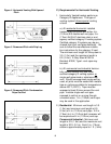
8.) Support the venting (flue) system by screw- GAS CONNECTION
ing three (3) sheet metal screws into each
pipe connection and then supporting at
WARNING: NEVER USE AN
maximum intervals of 4ft. (1.2m) to prevent OPEN FLAME TO CHECK FOR
sagging (in Canada, support every 3ft. (1.0m) GAS LEAKS. IF THERE IS
A
minimum intervals). GAS LEAK, EXPLOSION
OR INJURY CAN OCCUR.
A
LWAYS CHECK FOR LEAK
S
USING A SOAP SOLUTION.
10