


meter, making sure all other appliances are If the re
g
ulator needs ad
j
ustment, the re
g
ulator
turned off. adjusting screw may be turned clockwise to
The test hand on the meter should be timed for increase the pressure or counterclockwise to
at least one (1) revolution. Note the number of decrease the manifold pressure by more than
seconds for one (1) revolution. Use this formula or less than 0.3" w.c.
(
8.7kPa
)
.
to obtain the BTU/Hr input rate:
BTU/Hr = (Ft³/rev. ÷ No. sec./rev.) x 3600 Method B - Pressure Method
x Heating Value This method determines the input rate by
measuring the gas pressure in the manifold in
Your local utility or gas supplier can give you the inches water column.
heating value needed. However, the following Proceed as follows:
representative values may be used:
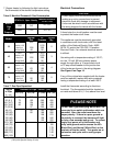
GAS BTU/FT³ 1.) Find the correct manifold pressure shown
Natural 1000 - 1150 in Table 6 on page 13.
LPG (Propane) 2500
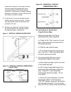
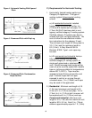
2.) Locate the combination control inside the
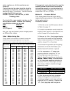
Also, you may use Table 5 (meter-timings) based heater and then push in on the ON/OFF lever
on different size meters. so that it snaps to the closed position.
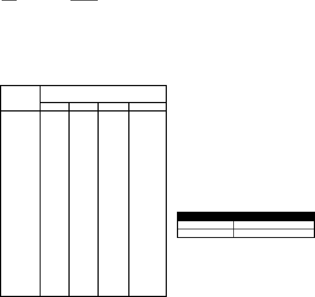
Table 5 Meter-timing Gas 3.) Remove the 1/8in. (.3cm) plugged tapping
(Timing required for one revolution is charted for various size from outlet of the control and then attached
meter dials and various rate of gas input in cu. ft. per hour. either a water manometer or "U" shape tube
To convert to Btuh, multiply by the heating value of the gas used.) which is at least 12 in. (.3cm) high.
Time for 1
4.) Put heater into operation per the lighting
1/2 F³ 1 Ft³ 2 F³ instructions and set the thermostat up so
10 180 360 720 that the heater will continue to operate.
12 150 300 600
14 129 257 514 5.) If the manometer or "U" shape tube
16 112 225 450 pressure indication is less than 1/2" w.c.
18 100 200 400 (1.3cm) higher or lower than shown in
20 90 180 36 Table 6, adjust the regulator as described in
22 82 164 327
Method A Meter Timin
g
. If the manometer
24 75 150 300 or "U" shape tube pressure indication is
26 69 138 277 more than 1/2" w.c (1.3cm) higher or lower
28 64 129 257 than shown in Table 6, check the inlet gas
30 60 120 240 pressure at heater.
35 51 103 206
40 45 90 180
45 40 80 160
50 36 72 144
55 33 65 131
60 30 60 120
6.) After adjustment has been completed,
70 26 51 103 make sure the gas flow is shutoff at the
80 22 45 90 heater by pressing in on the lever so that it
90 20 40 80 snaps to the OFF position. Replace the
100 18 36 72 1/8" (.3cm) plug taps and turn gas on.
120 15 30 60
180
150
300
257
225
200
360
Propane Gas 12 - 14" w.c. (3-3.5 kPa)
327
450
A
pplicatio
n
Gas Inlet Pressures
400
Natural Gas 6 - 7" w.c. (1.5-1.7 kPa)
692
643
600
514
1000
900
818
750
1800
1500
1286
1125
Input, Cu. Ft. per Hour, when meter dial size is:
Revolution
(Seconds) 5 Ft³
12