


SAFETY DEVICES (Continued) LED DIAGNOSTIC CAPABILITY
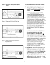
3) Pressure Switch The red LED on the ignition module indicates the
This is a normally open type switch which monitors condition of the control system. The following
the venting system. When the inducer motor codes indicate what type of failure is occurring
speeds up to produce enough vacuum in the venting and are also shown on the module.
system, the contacts in the pressure switch close
to complete the circuit to the ignition system. If for
some reason the inducer motor fails to operate or
should the venting system becomes blocked, the
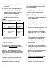
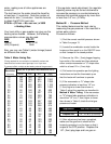
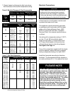
No Power/Internal Fault
pressure switch contacts open and the unit will not
operate.
Ignition Trail Lockout
Pressure Switch
If the pressure switch contacts do not close,
check the following:
TROUBLESHOOTING INFORMATION
1. Verify that venting system does not elbow
within 12" of the 3" dia. vent connect at rear of There are a few basic troubleshooting items that
the appliance. you may perform if, for some reason, the heater
does not operate. All other troubleshooting MUST
2. Check venting system for blockage. Remove BE DONE BY A QUALIFIED TECHNICIAN.
the obstruction(s).
A. If the heater does not light:
3. Check to make sure the tube between the 1. Make sure the thermostat is set above the
power exhaust and the pressure switch is secured room temperature.
and has not deteriorated. If bad, replace. 2. Make sure there is power to the heater.
3. Make sure the main gas supply is on at the
4. See if there is air flow at the vent terminal. Re- manual shut-off valve.
place pressure switch if there is air flow. Replace 4. If none of the above solve the problem, con-
the power exhauster if there is no air flow. tact a qualified technician.
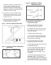
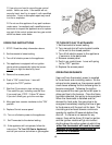
4) Hot Surface Ignitor B. Air feels cold coming out of the heater.
the ignitor is made from a ceramic material which 1. Make sure burner is lit.
must glow red hot until it reaches a required 2. If the room was cold to begin with, it will take
temperature to ignite the gas flowing through the a while for the air coming out of the heater to
burners. If the igniter does not glow red hot, check feel warm.
the resistance. If less than 100 Ω (ohms), replace 3. If the air coming out of the heater continues
the igniter. to feel cold after 5 minutes and the room is not
warming up, contact a qualified technician.
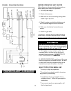
To replace, disconnect the leads S1 and S2 from
the module and remove the two (2) screws holding
the igniter to the burner box cover. Be very care-
ful when installing a new igniter as they can If a qualified service person cannot solve the
break easily. Re-connect leads to S1 and S2 on
problem, consult your local gas company or the
the module manufacturer.
Steady OFF
2 Flash
3 Flash
ADDENDUM - Page 18
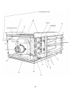
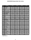
SERVICING AND REPAIR
Flame Sensed out of Sequence 1 Flash
When servicing, repairing or replacing parts on the unit,
always give the complete Model and Serial numbers
from the unit rating plate located inside the unit on the
panel in front of the burners.
ERROR MODE LED INDICATION
Normal Operation Steady ON
18