


8 | Hamilton Beach Owner’s Manual
Hamilton Beach Owner’s Manual | 9
Detailed Installation Instructions
General Installation Warnings
The following general warnings should be observed when
installation and/or general service maintenance is performed.
• Plumbing connections should be done in
accordance with state and local plumbing codes.
• Do not use with water that is microbiologically
unsafe or of unknown quality without adequate
disinfection before or after the system.
• Drain lines should be ” minimum for drain line
flows up to 7 gpm. Flows above 7 gpm or runs in
excess of 20 feet require ” drain line.
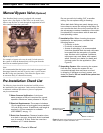
WARNING: Never connect drain line directly into a drain, sewer line or
trap. Plumbing code requires installation to allow an air gap* between the
drain line and the wastewater to prevent the possibility of sewage back-
siphoning into the conditioner. (See Figure 6.) Sewage backup can have
harmful health effects.
* Plumbing code air gap is one inch above the flood plane.
• All electrical connections must be connected
according to local codes. The electrical source
must be uninterrupted. Install grounding strap on
metal pipes.
• Do not use pipe dope or other types of liquid
sealants on any threads. Teflon tape must be used
on the drain line ” threads and also on the
3
/8”
brine-line connections.
Note: Factory has teflon taped these fittings.
• Use caution if soldering inlet, outlet, or drain lines.
Excess heat will damage the control valve and/or
bypass valve.
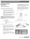
• A Brine Tank over-flow line of ” ID
5
/8” OD is
recommended for the brine tank. This line should
run from the barb fitting on the side of the tank to
an unobstructed drain. (See Figure 7.)
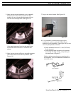
• Each system comes standard with a high-pressure
injector.* It may be necessary to change the
injector (see Figure 8) to match your incoming
water pressure. (See Table 2 for injector sizes.)
*Standard Injector (High Pressure)
Detailed Installation
Instructions
Injector Selection
Water Pressure Injector Part Number
20–60 psi
(138–414 bar)
AVP-1032980 (#5 Injector)
61–120 psi
(420–827 bar)
AVP-1032977 (#4 Injector)
Table 2: Injector selection based on water pressure.
Figure 6: Correct air-gap installation.
Overflow fitting
installed
Connect
1
/2” (1.3 cm) ID tubing
or hose and run to drain.
Brine tank
Figure 7: Brine tank tubing connection with overflow fitting.
Figure 8: Injector screen and cap installation.
Injector
Injector cap
Injector