


to the area adjacent to the water heater or to lower floors of
the structure (see “IMPORTANT” notice on the previous
page). Before installing this water heater, consideration and
planning must be given to the following details:
• Proximity to walls and other objects (see “Clearance and
Accessibility”).
• Access to gas supply (see “Gas Supply”).
• Routing and support of the vent piping and termination
(see “Venting”).
• Position of water supply and placement of water piping
and floor drain (see “Water Supply”).
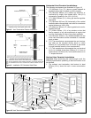
In Earthquake Zones
Note: The water heater must be braced, anchored, or
strapped to avoid moving during an earthquake. Contact
local utilities for code requirements in your area.
Note: The water heater may be installed in a closet with a
door off a bedroom or bathroom providing the units are
installed and vented per the manufacturer’s instructions.
Important: If installing over carpeting, the carpeting must
be protected by a metal or wood panel beneath the water
heater. The protective panel must extend beyond the full
width and depth of the water heater by at least 76mm (3 in.)
in each direction or if in an alcove or closet installation, the
entire floor must be covered by the panel.
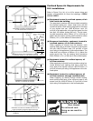
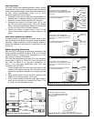
Clearances and Accessibility
• The minimum clearances between the heater and com-
bustible materials are:
Top . . . . . . . . . . . . . 200mm (8 in.)
Front . . . . . . . . . . . 100mm (4 in.)
Rear and Sides . . . 25mm (1 in.)
Note: These requirements are also listed on the data plate
located on the front of the water heater.
• The water heater is certified for installation on a com-
bustible floor.
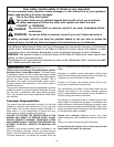
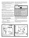
Figure 2 may be used as a reference guide to locate the
specific clearance locations. A minimum of 600mm (24 in.)
of front clearance and 100mm (4 in.) on each side should be
provided for inspection and service.
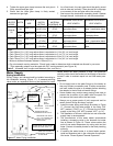
Gas Supply
Read the data plate to be sure the water heater is made
for the type of gas you will be using in your home. This
information will be found on the data plate located above the
gas control valve. If the information does not agree with the
type of gas available, do not install or attempt to start. Call
your dealer.
Note: An odourant is added by the gas supplier to the gas
used by this water heater. This odourant may fade over an
extended period of time. Do not depend upon this odourant
as an indication of leaking gas.
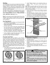
FRONT 600mm
(24 in.) MIN.
FOR SERVICE
BACK
AIR INTAKE *
SENSOR *
SIDES
SIDES
VENT
TOP TO
CEILING
* DO NOT BLOCK AIR INTAKE OR SENSOR ACCESS. ENSURE ADEQUATE
CLEARANCE FOR AIR SUPPLY
Figure 2 Minimum Clearance Locations
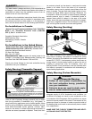
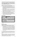
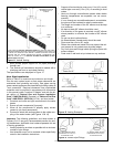
DANGER
Explosion Hazard
• Use a new CSA approved gas supply line.
• Install a gas supply shut-off valve.
• Do not connect a natural gas water heater
to a L.P. gas supply.
• Do not connect a L.P. gas water heater to
a natural gas supply
• Failure to follow these instructions can
result in death, an explosion or carbon
monoxide poisoning.
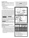
Figure 3 Gas Piping
DRIP LEG
MANUAL
GAS
SHUT-OFF
GAS
CONTROL/
THERMOSTAT
76mm
(3 in.)
GROUND-
JOINT UNION
– 7 –