


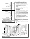
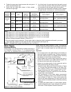
4. Tighten the upper gear clamp to ensure the vent pipe is
firmly secured and gas tight.
5. Check that the lower gear clamp is firmly seated,
secured and gas tight.
6. As a final check, the vent pipe should be gently moved
side to side and vertically. There should be no slippage
or movement of the vent pipe within the coupling.
7. Seal around the termination assembly where it passes
through the wall, inside and out, with silicone sealant.
WATER
HEATER
MODEL
SUFFIX
VENT PIPE
SIZE
PRESSURE
SWITCH
SETTING
* VENT
MATERIAL
(SCHEDULE 40)
MAXIMUM EQUIVALENT
VENT LENGTH
MINIMUM EQUIVALENT
VENT LENGTH
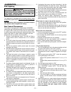
NVH,
PVH
50mm (2 in.)
- 0.15 in. w.c.
(-0.037 kPa)
ABS, PVC**,
CPVC
15.2m (50 ft.) +
termination elbow
0.76m (2.5 ft.) + one 90°
elbow + termination elbow
NVH,
PVH
76mm (3 in.)
- 0.15 in. w.c.
(-0.037 kPa)
ABS, PVC**,
CPVC
24.4m (80 ft.) +
termination elbow
15.2m (50 ft.) +
termination elbow
G/JW5065
SNV,
SPV
76mm (3 in.)
- 0.55 in. w.c.
(-.137 kPa)
ABS, PVC,
CPVC
15.2m (50 ft.) +
termination elbow
0.91m (3 ft.) + one 90°
elbow + termination elbow
G/JW5065 LNV 76mm (3 in.)
- 0.50 in. w.c.
(-.124 kPa)
ABS, PVC,
CPVC
19.8m (65 ft.) +
termination elbow
6.9m (20 ft.) + termination
elbow
G/JW40,
50
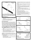
Notes:
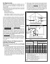
1. Each 50mm (2 in.), 90° long radius elbow is equivalent to 1.5m (5 ft.) of vent length.
2. Each 76mm (3 in.), 90° long radius elbow is equivalent to 2.1m (7 ft.) of vent length.
3. Each 50mm (2 in.), 45° long-radius elbow is equivalent to 0.9m (3 ft.) of vent length.
4. Each 76mm (3 in.), 45° long radius elbow is equivalent to 1.2m (4 ft.) of vent length.
5. Minimum distance between elbows is 150mm (6 in.).
6. Do not mismatch venting materials. *Check local codes to determine which materials are allowed in your area.
7. **Pipe assembly adaptor must be used with PVC venting material (see Figure 14).
Table 2 Allowable Vent Lengths and Materials (Vert. and Horiz.).
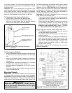
Water Supply
Piping Installation
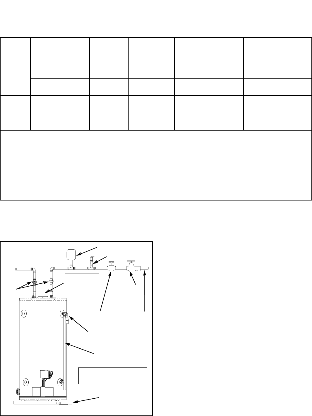
Piping, fittings, and valves should be installed according to
the installation drawing (Figure 17). A pressure-reducing
valve and/or an expansion tank may be required for instal-
lations where the water pressure is high. The pressure-
reducing valve should be located on the supply to the entire
house in order to maintain equal hot and cold water pres-
sure.
Important:
• Do not apply heat to the water fittings on the heater as
they may contain nonmetallic parts. If solder connections
are used, solder the pipe to an adaptor before attaching
the adaptor to the hot and cold water fittings.
• Some models may contain energy saving heat traps to
prevent the circulation of hot water within the pipes. Do
not remove the inserts within the heat traps.
• Always use a proper grade of joint compound and be
certain that all fittings are drawn up tight.
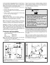
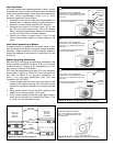
1. Install the water piping and fittings as shown in Figure
17. Connect the cold water supply to the fitting (3/4”
NPT) marked “COLD” (or “C”). Connect the hot water
supply to the fitting (3/4” NPT) marked “HOT” (or “H”).
2. The installation of unions in both the hot and cold water
supply lines is recommended.
3. The manufacturer of this water heater recommends
installing a tempering valve in the domestic hot water
line as shown in Figure 18. These valves reduce the
point-of-use water temperature by mixing cold and hot
water. Contact a licensed plumber or the local plumbing
authority.
4. If installing the water heater in a closed water system,
install an expansion tank in the cold water line as spec-
ified under “Closed System/Thermal Expansion”.
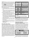
COLD WATER
INLET
COLD WATER
INLET VALVE
PRESSURE
REDUCING
VALVE
WITH
BYPASS
TEMPERATURE AND
PRESSURE RELIEF VALVE
HOT
WATER
OUTLET
UNION
DRAIN PAN CONNECT TO
PROPERLY OPERATING
FLOOR DRAIN.
DISCHARGE LINE 300mm
(12 in.) max (CANADA) OR
150mm (6 in.) max (U.S.)
ABOVE DRAIN
IN A CLOSED SYSTEM USE EITHER: 1.THERMALEXPANSION TANK
OR
2.PRESSURE RELIEF VALVE.
Figure 17 Water Piping Installation
MASSACHUSETTS: INSTALL A
VACUUM RELIEF IN COLD WATER
LINE PER SECTION 19MGL 142
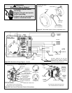
NOTE: BLOWER
ASSEMBLY NOT
SHOWN FOR
CLARITY.
– 15 –