


First Lighting
This appliance is equipped with an ignition device, which
automatically lights the pilot. Do not try to light manually with
a match.
The temperature dial is adjusted to its lowest tempera-
ture position when shipped from factory.
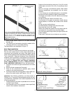
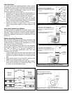
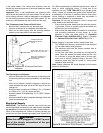
Gas Control/Thermostat
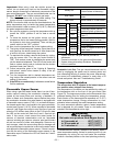
This heater is equipped with a Robertshaw 2000WDER
combination gas control/thermostat and a hot surface ignit-
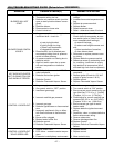
er. A green LED on the front of the control is used to flash
a system status code indicating the operational state of the
control (see Table 3). When initially energized, with tem-
perature dial set at vacation, the control will:
1. Perform a self-diagnostic check. The LED will flash a
system status code to indicate that it is in vacation
mode.
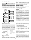
2. On a call for heat, the control checks to ensure the air
pressure switch on the blower is in the open position. If
closed the sequence pauses and the blower is not ener-
gized.
3. With the air pressure switch proven open, the control
energizes the blower.
4. With the blower energized the control checks to ensure
the air pressure switch closes. At this point the air pres-
sure switch must close or the blower will run continu-
ously.
5. The high limit switch on the blower is wired in series
with the air pressure switch, so both switches must be
closed or the blower will run continuously. With proven
airflow and the high limit switch closed, a flame safety
check is undertaken to ensure a flame is not present
prior to ignition.
6. Providing a flame present signal is not detected, the hot
surface igniter is energized and a warm up period of
approximately 17 seconds is initiated.
7. Following the igniter warm up period, the control allows
gas to flow to the burner initiating a 4 second trial for
ignition period.
8. If a flame cannot be established within the trial for igni-
tion period, is extinguished or the flame signal drops
below 0.7 microamps, the control will stop the flow of
gas to the burner.
9. The blower continues to be energized and a 30 second
inter-purge is undertaken.
10. The control will attempt for ignition again. If a flame can-
not be established after three attempts, it will go into a
soft lockout state.
11. The LED on the control will flash a system status code
indicating the lockout state due to ignition failure (see
Table 3).
12. Unplugging the power cord then reinserting it into the
electrical receptacle will reset the control. Alternatively,
the control will automatically reset itself approximately
20 minutes after entering the soft lockout state.
13. The control will normally establish a flame and maintain
the flame until the call for heat is satisfied.
14. After the burner is lit, the gas control/thermostat will
electronically monitor the presence of a flame.
15. When the desired water temperature has been
reached, the gas control/thermostat will stop the flow of
gas to the burner.
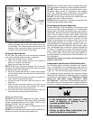
When heater is ready to be put into service:
1. Turn the manual gas shut-off valve to the “ON” position.
2. Turn the gas control switch to “ON”.
3. Smell all around the appliance area for gas. Be sure to
smell next to the floor because some gases are heavier
than air and will settle on the floor.
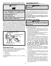
What to Do If You Smell Gas
• Turn the manual gas shut-off valve to the “OFF” position.
• Do not try to light any appliance.
• Do not touch any electric switch; do not use any phone
in your building.
• Evacuate all occupants from your building.
• Immediately call your gas supplier from a neighbor’s
phone. Follow the gas supplier’s instructions.
• If you cannot reach your gas supplier, call the fire depart-
ment.
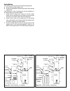
If You Do Not Smell Gas
1. Turn the temperature dial to the lowest setting and set
the gas control switch to the “OFF” position.
2. Ensure the power cord is plugged into the electrical
receptacle and correct voltage is supplied to the appli-
ance.
3. With the gas control switch “OFF”, check the pressure
of the gas supply to the control:
Natural Gas pressure should be at 7 in. w.c. (1.74
kPa).
Propane Gas pressure should be at 11 in. w.c. (2.73
kPa).
4. Turn the gas control switch to “ON”.
5. Turn the temperature dial to the desired setting, (e.g.,
from “VACATION” toward “HOT”). This will start the
lighting process:
a. The blower will be turned on after 20 seconds.
b. The igniter will be at full glow after the next 17 sec-
onds.
c. The main gas valve opens.
d. The burner lights up, the flame envelops the flame
sensor, and the burner flame verification process
begins.
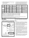
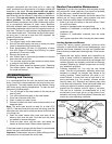
6. While the burner is on, again check all gas connections
with a chloride-free soap and water solution or equiva-
lent leak test liquid. Correct any poor connections that
may be indicated by the presence of soap bubbles.
Shut off electric and gas supply before making
such corrections.
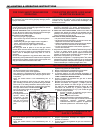
CAUTION:
Read before proceeding. If you do not follow
these instructions exactly, a fire or explosion
may result, causing property damage, per-
sonal injury or loss of life.
V) OPERATION
– 21 –