


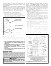
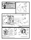
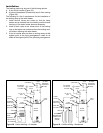
Water Heater Operation
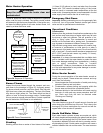
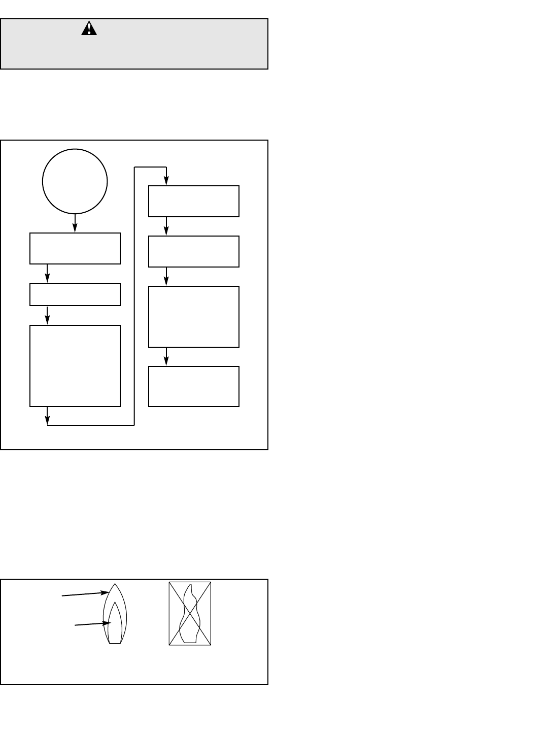
Figure 24 shows the water heater’s sequence of operation
when a call for heat is initiated. The ignition control module
will attempt to light the burner three times. If the ignition con-
trol does not detect ignition it will enter lockout mode, indi-
cated by a three flash error code.
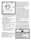
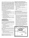
Burner Flames
Inspect the burner flames through the viewport and com-
pare them to the drawings in Figure 25. A properly operat-
ing burner should produce a soft blue flame. Blue tips with
light blue inner cones are satisfactory. The tips of the flame
may have a slight yellow tint. The flame should not be all
yellow or have a sharp blue-orange colour. Contaminated
air may cause an orange coloured flame. Contact a qualified
service technician if the flame is not satisfactory.
Stacking
Stacking occurs when a series of short draws of hot water
(11 litres (3 US gallons) or less) are taken from the water
heater tank. This causes increased cycling of the burner
and can result in increased water temperatures at the hot
water outlet. A tempering device is recommended in the hot
water supply line to reduce the risk of scald injury.
Emergency Shut Down
Important: Should overheating occur or the gas supply fails
to shut off, turn off the water heater’s manual gas control
valve and call a qualified service technician.
Operational Conditions
Condensation
Moisture from the products of combustion condenses on the
tank surface and forms drops of water which may fall onto
the burner or other hot surfaces. This will produce a “siz-
zling” or “frying” noise. This condensation is normal and
should not be confused with a leaking tank. Condensation
may increase or decrease at different times of the year.
High efficient energy saver water heaters will produce larg-
er amounts of condensation on initial start-up or when a
large amount of hot water is being used. Do not confuse this
with a “tank leak”. Once the water reaches a temperature of
49°C (120°F) and the tank warms up (usually 1-2 hours),
the condensation will stop.
Important: It is always recommended that a suitable drain
pan be installed under the water heater to protect the area
from water damage resulting from condensation, a leaking
tank or piping connections. Refer to “Location
Requirements”. Under no circumstances is the manufactur-
er to be held responsible for any water damage in connec-
tion with this water heater.
Water Heater Sounds
During the normal operation of the water heater, sounds or
noises may be heard. These noises are common and may
result from the following:
1. Normal expansion and contraction of metal parts during
periods of heat-up and cool-down.
2. Condensation causes sizzling and popping within the
burner area and should be considered normal.
3. Sediment buildup in the tank bottom will create varying
amounts of noise and may cause premature tank fail-
ure. Drain and flush the tank as directed under
“Draining and Flushing”.
Smoke/Odour
The water heater may give off a small amount of smoke and
odour during the initial start-up of the unit. This is due to the
burning off of oil from metal parts of a new unit and will dis-
appear after a few minutes of operation.
Anode Rod/Water Odour
Each water heater contains at least one anode rod, which
will slowly deplete while protecting the glass-lined tank from
corrosion and prolonging the life of the water heater. Once
the anode is depleted, the tank will start to corrode, eventu-
ally developing a leak. Certain water conditions will cause a
reaction between this rod and the water. The most common
WARNING:
Keep the area around the heater clear and
unobstructed.
CORRECT FLAME
SOFT BLUE
INCORRECT
FLAME LAZY
YELLOW
Figure 25 Flame Characteristics
BLUE TIPS
LIGHT BLUE INNER
CONES ARE SATIS-
FACTORY
CONTROL CHECKS TO
ENSURE PRESSURE
SWITCH IS OPEN
BLOWER IS
ENERGIZED
CONTROL CHECKS TO
ENSURE PRESSURE
SWITCH CLOSES
INDICATING BLOWER
IS OPERATING AND
THERE ARE NO
VENTING BLOCKAGES
(INLET OR OUTLET)
IGNITER IS
ENERGIZED AND MAIN
VALVE IS OPENED
MAIN BURNER ON AND
THE FLAME IS
SENSED BY CONTROL
MAIN BURNER
CONTINUES TILL THE
WATER IN THE TANK
REACHES
THERMOSTAT
SETTING
MAIN BURNER SHUTS
OFF. BLOWER
CONTINUES FOR A
POST PURGE TIME
CALL
FOR HEAT
INDICATED BY
FAST FLASH
OF LED
Figure 24 Sequence Of Operation
– 23 –