


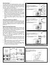
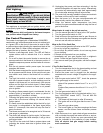
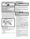
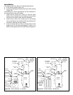
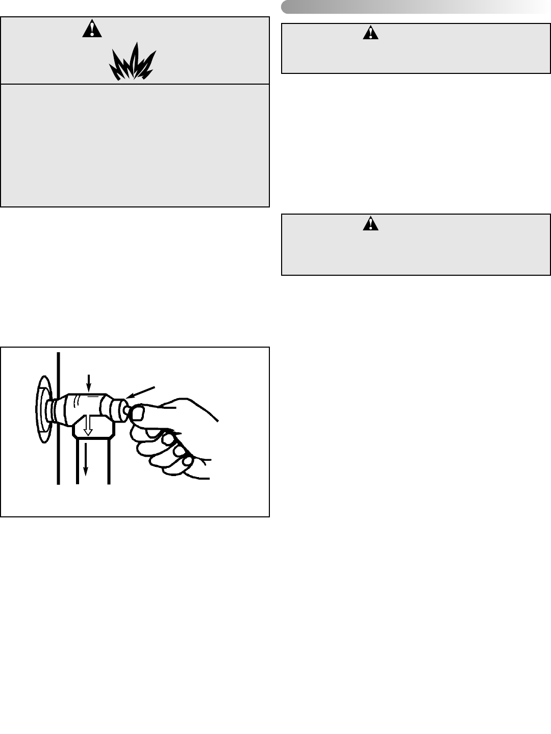
Temperature and Pressure Relief Valve
Manually operate the temperature and pressure relief valve
at least once a year to make sure it is working properly (see
Figure 27). To prevent water damage, the valve must be
properly connected to a discharge line that terminates at an
adequate drain. Standing clear of the outlet (discharged
water may be hot), slowly lift and release the lever handle
on the temperature and pressure relief valve to allow the
valve to operate freely and return to its closed position. If the
valve fails to completely reset and continues to release
water, immediately shut off the manual gas valve and the
cold water inlet valve and call a qualified service technician.
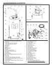
Replacement Parts
Replacement parts may be ordered through your plumber or
the local distributor. When ordering replacement parts,
always have the following information ready:
1. model, serial and product number
2. type of gas
3. item number
4. parts description
See “Replacement Parts Illustration” for a list of available
repair parts.
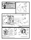
This section serves as a guide for the installation and use of
“Combo” heating systems utilizing a domestic water heater
that has been specifically approved for such use. It is writ-
ten for those knowledgeable in the required trades and pro-
fessionals involved in the design and installation of Combo
Heating Systems.
It is the responsibility of the installer/designer to follow
all applicable codes to ensure the effectiveness and
safety of the installation.
Read Before Proceeding
The following requirements must be met for the installation
of Combo Heating Systems:
1. All components used for the distribution of water in the
heating loop must be suitable for potable water. These
include all piping, fittings, solder and fluxes, pumps for
circulation of water, valves, etc.
2. The water heater must not be connected to a hydronic
heating system that has been used previously.
3. No boiler treatment chemicals of any kind shall be intro-
duced into the system.
4. The Combo System components must be selected and
sized to meet and maintain the total calculated
demands for both domestic service hot water and space
heating requirement. The sizing and installation must be
performed in accordance with good engineering prac-
tice such as “ASHRAE Handbooks”, HRAI,
“Hydronics Institute Manuals”, CSA B149.1, NFPA
54, ANSI Z223.1, CSA F280, National/Provincial
Building Codes, CSA C22.1, ANSI/NFPA 70, CSA
B51 and/or codes having jurisdiction.
5. The air handler (fan coil) and/or the circulating pump in
a baseboard hydronic loop will require a dedicated
120V circuit. This must be provided and identified for
this purpose.
6. All piping between the water heater and the air handler
or hydronic baseboard loop must be adequately insulat-
ed to reduce heat loss.
7. If the local jurisdiction requires a back-flow preventer in
the cold water line, an expansion tank of adequate size
must be installed.
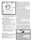
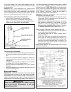
8. “Combo” Heating Systems require higher water temper-
atures than other applications. When the system is
used to supply water for Combo Heating applications, a
means, such as mixing valve, must be installed to tem-
per the water in order to reduce scald hazard potential
(see Figures 28 & 29).
VII) COMBO HEATING
WARNING:
Keep the area around the heater clear and
unobstructed.
Temperature and Pressure
Relief Valve
Manual Relief Valve
Discharge line to drain
Figure 27 T&P Valve Test
WARNING
Explosion Hazard
• If the temperature and pressure relief
valve is dripping or leaking, have a
licensed plumber repair it.
• Do not plug valve.
• Do not remove valve.
• Failure to follow these instructions can
result in death or an explosion.
CAUTION:
Keep safety your first priority. Take all pre-
cautions to avoid creating a fire, health or
safety hazard.
– 25 –