


2. Must provide proper support for all pipes protruding
through roof.
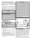
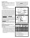
3. The vertical roof terminations should be sealed with a
plumbing roof boot or equivalent flashing.
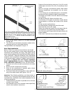
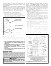
The specifications are displayed in Figure 11.
Vent Pipe Installation
Refer to Table 2 for maximum and minimum vent length.
Plan the vent system layout so that proper clearances are
maintained from plumbing and wiring. Vent pipes serving
power vented appliances are classified by building codes as
"vent connectors". Required clearances from combustible
materials must be provided in accordance with information
in this manual under "Location Of Heater" and with the lat-
est edition of "Natural Gas and Propane Installation
Code" CAN/CSA-B149.1 (Canada), or "National Fuel Gas
Code" ANSI Z223.1 (NFPA 54) (U.S.A.) and local codes.
1. Construct and route vent pipe connections to the water
heater.
2. Ensure all vent components fit properly.
3. When all the components fit properly apply solvent
cement to join them permanently.
4. Proceed to attach the venting system to the rubber cou-
pling of the water heater (see Figures 15 & 16).
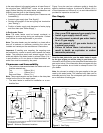
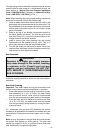
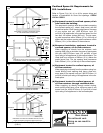
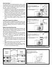
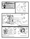
Important: The following guidelines, and those shown in
Figures 12 & 13 are good, recommended practice for vent-
ing installations. Applicable local codes supersede this set
of venting guidelines:
• Venting should be as direct as possible with a minimum
number of pipe fittings.
• Vent diameter must not be reduced unless specifically
noted in the installation instructions.
• Support all horizontal pipe runs every 1.2m (4 ft.) and all
vertical pipe runs every 1.5m (5 ft.) or according to local
codes.
• Vents run through unconditioned spaces where below
freezing temperatures are expected, are not recom-
mended.
• If a run through an unconditioned space is unavoidable,
the pipe must be insulated to reduce condensation.
• The length and number of the 90° elbows must be kept
to a minimum.
• No back-to-back 90° elbows should be used.
• If re-direction of flue gases is required, use 45° elbows
where possible, to minimize the number of 90° elbows
used.
• Do not use short radius elbows.
• No Street elbows (female-male) should be used.
• Pipes must be cut at a 90° angle.
• Deburr the outside and inside of the cut pipe so that sol-
vent cement is not pushed away by sharp edges.
• Dry fit all pipes and fittings before joining the parts with
solvent cement.
• Parts must fit well and not put stress on any sections.
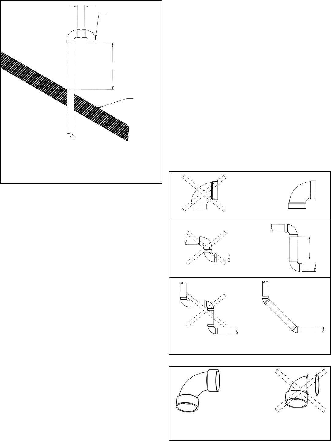
TERMINATION MAY BE
90° ELBOW OR A “T”
ELBOW
76mm (3 in.)
MIN. LENGTH
ROOF
LINE
450mm (18 in.)
Figure 11 Vertical Venting
A VENT USED IN A SPECIAL VENTING SYSTEM WITH POSITIVE VENT PRES-
SURE AND PASSING THROUGH AROOF SHALL EXTEND AT LEAST450mm (18
in.) ABOVE THE HIGHEST POINT WHERE IT PASSES THROUGH THE ROOF
SURFACE AND ANY OTHER OBSTRUCTION WITHIN A HORIZONTAL DIS-
TANCE OF 450mm (18 in.). A VERTICAL VENTING SYSTEM MUST BE SUP-
PORTED EVERY 2.4m (8 ft.).
PREFERRED PRACTICE
Figure 12 Venting Examples
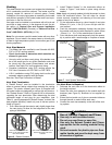
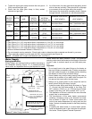
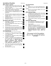
150mm
(6 in.) min.
STREET ELBOW NORMAL ELBOW
BACK TO BACK ELBOWS
Figure 13 Correct Pipe Fittings
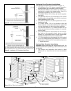
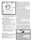
90° LONG SWEEP ELBOW
EQUIVALENT TO 1.5m (5 ft.)
OF STRAIGHT PIPE
90° SHORT SWEEP ELBOW
EQUIVALENT TO 2.4m (8 ft.)
OF STRAIGHT PIPE
– 13 –