


Installation
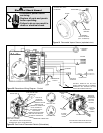
The heating mode may be one of the following options:
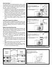
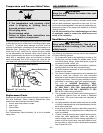
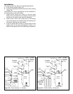
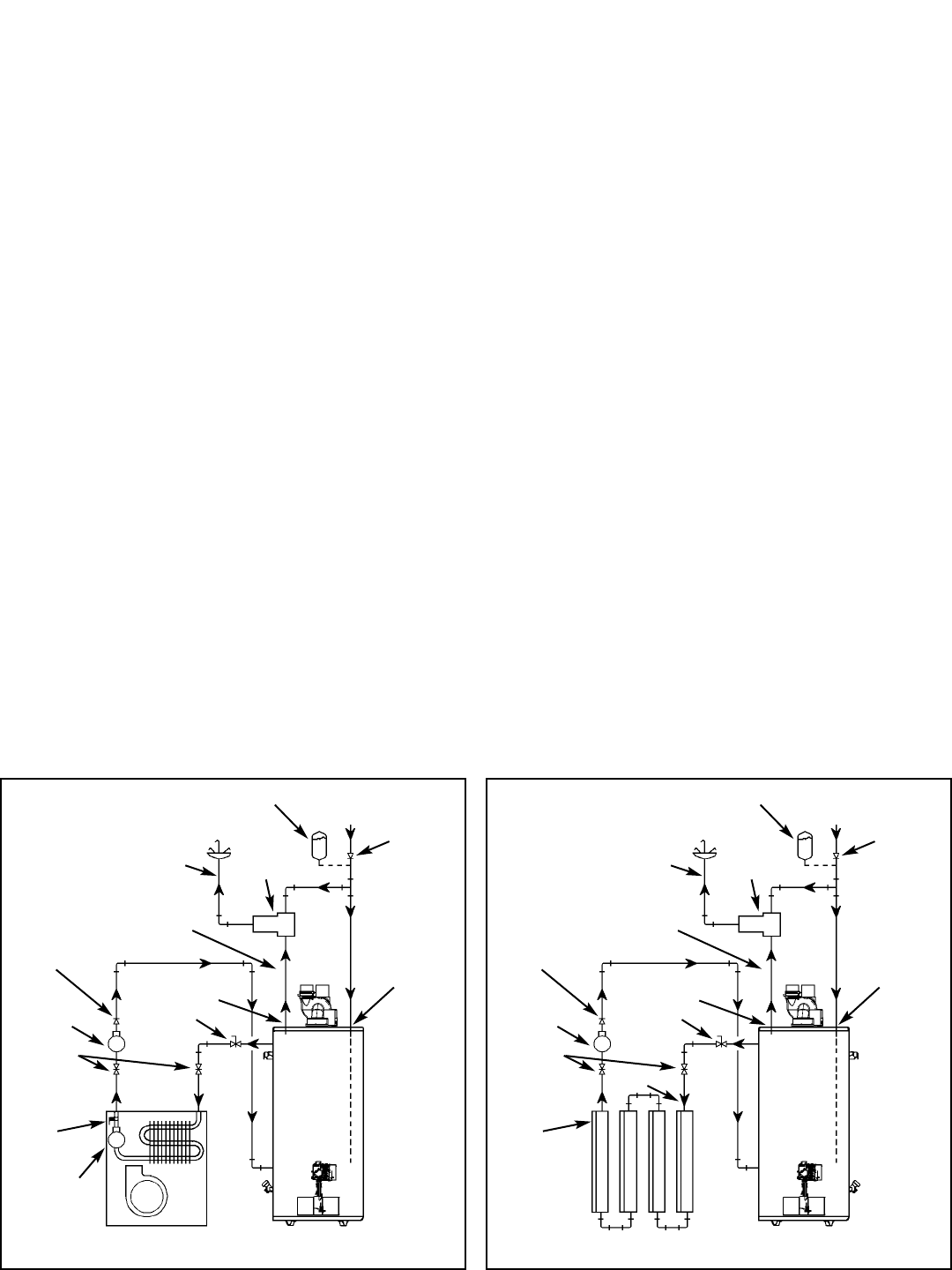
A. A fan coil/air handler (Figure 28).
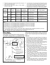
B. A hydronic baseboard (finned tube) loop/In floor heating
(Figure 29).
The following is a list of requirements for the installation of
the heating loop to the water heater.
1. Install shut-off valves and unions so that the water
heater can be isolated from the heating module should
servicing of the water heater become necessary.
2. Install a drain valve at the lowest point of the heating
loop so that water can be drained from the heating mod-
ule without affecting the water heater.
3. If the air handler does not have a venting means at the
highest point of the piping arrangement, install an air
bleed at the highest point of the plumbing arrangement.
WATER
HEATER
8in TO 12in
MAX.
HOT
OUTLET
EXPANSION TANK
(OPTIONAL)
MIXING
VALVE
COLD
INLET
CHECK VALVE
(IF USED
REQUIRES
EXPANSION
TANK)
COLD
SUPPLY
HOSE BIB
(OPTIONAL)
FLOW
CONTROL
SUPPLY
RETURN
CHECK
VALVE
EXTERNAL
CIRCULATOR
AIR HANDLER
HOT WATER
TO HOUSE
FIXTURE
C
H
M
INTERNAL
CIRCULATOR
DRAIN/PURGE
VALVE
Figure 28 Combo Heating - Air Handler
WATER
HEATER
8in TO 12in
MAX.
HOT
OUTLET
EXPANSION TANK
(OPTIONAL)
MIXING
VALVE
COLD
INLET
CHECK VALVE
(IF USED
REQUIRES
EXPANSION
TANK)
COLD
SUPPLY
HOSE BIB
(OPTIONAL)
FLOW
CONTROL
SUPPLY
RETURN
CHECK
VALVE
EXTERNAL
CIRCULATOR
HOT WATER
TO HOUSE
FIXTURE
C
H
M
HYDRONIC
BASEBOARDS
(SERIES CON-
NECTED
SHOWN)
Figure 29 Combo Heating - Baseboard
– 26 –