


49
If the last call for heat was a call for high heat, the air
circulating motor will run on the high heating speed for thirty
(30) seconds and then switch to the low heating speed for
the balance of the heat off delay period (60, 90, 120 or 150
seconds).
• Circulator blower and electronic air cleaner terminal is de-
energized.
• Circulator blower ramps down to OFF during the 30 seconds
following the heat off delay period.
• Furnace awaits next call from thermostat.
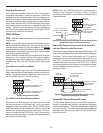
COOLING M ODE
The normal operational sequence in cooling mode is as follows:
• R and Y1/G or Y2/G thermostat contacts close, initiating a
call for cool.
• Integrated control module performs safety circuit checks.
• Outdoor fan and compressor are energized to their
appropriate speed.
• Circulator blower is energized on the appropriate cool speed
at the level and time determined by the selected ramping
profile. Electronic air cleaner terminal is energized with
circulator blower.
• Furnace circulator blower and outdoor cooling unit run their
appropriate speeds, integrated control module monitors
safety circuits continuously.
• R and Y1/G or Y2/G thermostat contacts open, completing
the call for cool.
• Outdoor fan and compressor are de-energized.
• Circulator blower continues running during a cool off delay
period. The OFF delay time and airflow level are determined
by the selected ramping profile.
• Electronic air cleaner terminal and circulator blower are de-
energized.
• Furnace awaits next call from thermostat.
FAN O NLY M ODE
The normal operational sequence in fan only mode is as follows:
• R and G thermostat contacts close, initiating a call for fan.
• Integrated control module performs safety circuit checks.
• Circulator blower is energized on continuous fan speed
(25%, 50%, 75% or 100% dip switch selectable when
using a conventional thermostat). Electronic air cleaner
terminal is energized.
• The IFC HUM dry contacts close.
• Circulator blower runs, integrated control module monitors
safety circuits continuously.
• R and G thermostat contacts open, completing the call for
fan.
• Circulator blower is de-energized. Electronic air cleaner
terminal is de-energized.
• Furnace awaits next call from thermostat.
O
PERATIONAL
C
HECKS
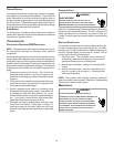
The burner flames should be inspected with the burner compart-
ment door installed. Flames should be stable, quiet, soft, and
blue (dust may cause orange tips but they must not be yellow).
Flames should extend directly outward from the burners without
curling, floating, or lifting off. Flames must not impinge on the
sides of the heat exchanger firing tubes.
Burner Flame
S
AFETY
C
IRCUIT
D
ESCRIPTION
A number of safety circuits are employed to ensure safe and proper
furnace operation. These circuits serve to control any potential
safety hazards and serve as inputs in the monitoring and diagno-
sis of abnormal function. These circuits are continuously moni-
tored during furnace operation by the integrated control module.
INTEGRATED FURNACE C ONTROL (IFC)
The integrated control module is an electronic device which, if a
potential safety concern is detected, will take the necessary pre-
cautions and provide diagnostic information through an LED dis-
play.
PRIMARY LIMIT
The primary limit control is located on the partition panel and moni-
tors heat exchanger compartment temperatures. It is a normally-
closed (electrically), automatic reset, temperature-activated sen-
sor. The limit guards against overheating as a result of insufficient
conditioned air passing over the heat exchanger.
AUXILIARY L IMIT
The auxiliary limit controls are located on or near the circulator
blower and monitors blower compartment temperatures. They are
a normally-closed (electrically), auto-reset sensors. These limits
guard against overheating as a result of insufficient conditioned air
passing over the heat exchanger.
ROLLOUT LIMIT
The rollout limit controls are mounted on the burner/manifold as-
sembly and monitor the burner flame. They are normally-closed
(electrically), manual-reset sensors. These limits guard against
burner flames not being properly drawn into the heat exchanger.