


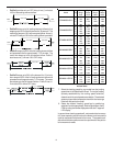
37
• If the differential is equal to or less than 2 degrees,
the IFC will follow the conventional 2-Stage algorithm,
equivalent to a W1 request and be reflected in the
Heat Current Demand Status %.
• If the heat differential is greater than 2 degrees, the
IFC will follow the conventional 2-Stage algorithm,
equivalent to a W2 request and be reflected in the
Heat Current Demand Status %.
• The circulator will operate per the heat airflow profile.
HEATING OPERATION WITH CTK02AA THERMOSTAT
(MODULATING C OMMUNICATING)
• When the Thermostat Heat Setup DIP switch is set
to 1-Stage heat, the IFC operation will be compatible
with a modulating communicating thermostat
(CTK02AA).
• When a call for heat is sent, the furnace will go through
the Light Off Sequence, at which time the Heat Current
Demand Status will still show 0%. After the successful
Light Off Sequence and expiration of the Ignition
Stabilization Period:
• The IFC adjusts to the low firing rate.
• After 2 minutes, the IFC accepts the specific Heat
Requested Demand.
• If the differential is 2 degrees or less, the Heat
Current Demand Status will show 50%.
• If the specific Heat Requested Demand is above 2
degrees, the Heat Current Demand Status will track
the specific Heat Requested Demand.
• The circulator will operate per the heat airflow profile.
HEAT A NTICIPATOR S ETTING
The heat anticipator in the room thermostat must be correctly
adjusted to obtain the proper number of cycles per hour and to
prevent “overshooting” of the setting. Set the heat anticipator set-
ting to 0.7 amps. Follow the thermostat manufacturer’s instruc-
tions on how to adjust the heat anticipator setting.
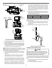
DRAIN T RAP P RIMING
The drain trap must be primed prior to furnace startup. To prime, fill
the drain trap with water. This ensures proper furnace drainage
upon startup and prohibits the possibility of flue gases escaping
through the drain system. Air conditioning condensate may be
drained into the furnace trap. Please see requirements in Con-
densate Drain Lines & Drain Trap section.
FURNACE O PERATION
Purge gas lines of air prior to startup. Be sure not to purge lines
into an enclosed burner compartment.
Check for leaks using an approved chloride-free soap and water
solution, an electronic combustible gas detector, or other approved
method. Verify that all required kits (propane gas, etc.) have been
appropriately installed.
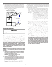
FURNACE S TARTUP
1. Close the manual gas shutoff valve external to the furnace.
2. Turn off the electrical power to the furnace.
3. Set the room thermostat to the lowest possible setting.
4. Remove the burner compartment door.
NOTE: This furnace is equipped with an ignition device which
automatically lights the burner. Do not try to light the burner by
hand.
5. Move the furnace gas valve manual control to the OFF
position.
6. Wait five minutes then smell for gas. Be sure check near
the floor as some types of gas are heavier than air.
7. If you smell gas after five minutes, immediately follow the
Safety Instructions on page 5 of this manual. If you do not
smell gas after five minutes, move the furnace gas valve
manual control to the ON position.
8. Replace the burner compartment door.
9. Open the manual gas shutoff valve external to the furnace.
10. Turn on the electrical power to the furnace.
11. Adjust the thermostat to a setting above room temperature.
12. After the burners are lit, set the thermostat to desired
temperature.
FURNACE S HUTDOWN
1. Set the thermostat to the lowest setting.
The integrated control will close the gas valve and extinguish
flame. Following a 15 second delay, the induced draft blower
will be de-energized. After a 120, 150, 180 or 210-second
delay period (field selectable delay OFF [90, 120, 150, 180]
plus 30-second ramp down), the circulator blower de-
energizes.
2. Remove the burner compartment door and move the furnace
gas valve manual control to the OFF position.
3. Close the manual gas shutoff valve external to the furnace.
4. Replace the burner compartment door.
GAS S UPPLY PRESSURE M EASUREMENT
CAUTION
T
O
PREVENT
UNRELIABLE
OPE RATION
OR
EQUIPMENT
DAMAGE
,
THE
INLET
GAS
SUPPLY
PRESSURE
MUST
BE
AS
SPECIFIED
ON
THE
UNIT
RATING
PLATE
WITH
ALL
OTHER
HOUSEHOLD
GAS
FIRED
APPLIANCES
OPE RATING
.
The line pressure supplied to the gas valve must be within the
range specified below. The supply pressure can be measured at
the gas valve inlet pressure boss or at a hose fitting installed in the
gas piping drip leg. The supply pressure must be measured with
the burners operating. To measure the gas supply pressure, use
the following procedure.