


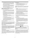
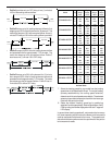


45
FOSSIL F UEL A PPLICATIONS
This furnace can be used in conjunction with a ComfortNet™
compatible heat pump in a fossil fuel application. A fossil fuel
application refers to a combined gas furnace and heat pump in-
stallation which uses an outdoor temperature sensor to determine
the most cost efficient means of heating (heat pump or gas fur-
nace). When used with the CTK0*AA thermostat, the furnace/
heat pump system is automatically configured as a fossil fuel
system. The balance point temperature may be adjusted via
the CTK0*AA thermostat advanced user menus (see CTK0*AA
instructions for additional information).
CTK0*AA WIRING
NOTE: Refer to Electrical Connections for 115 volt line connections
to the furnace.
NOTE: A removable plug connector is provided with the control to
make thermostat wire connections. This plug may be removed,
wire connections made to the plug, and replaced. It is strongly
recommended that multiple wires into a single terminal be twisted
together prior to inserting into the plug connector. Failure to do so
may result in intermittent operation.
Typical 18 AWG thermostat wire may be used to wire the system
components. One hundred (100) feet is the maximum length of
wire between indoor unit and outdoor unit, or between indoor unit
and thermostat. Wire runs over (100) feet require larger gauge
wire.
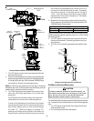
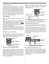
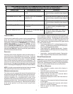
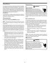
FOUR-WIRE I NDOOR AND O UTDOOR W IRING
Typical ComfortNet wiring will consist of four wires between the
indoor unit and outdoor unit and between the indoor unit and ther-
mostat. The required wires are: (a) data lines, 1 and 2; (b) thermo-
stat “R” (24 VAC hot) and “C” (24 VAC common).
12RC
12RC
CTK0*AA
Thermostat
ComfortNet Compatible Furnace
Integrated Control Module
ComfortNet Compatible AC/HP
Integrated Control Module
12RC
System Wiring using Four-Wires
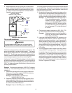
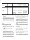
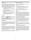
TWO-WIRE O UTDOOR, FOUR-WIRE I NDOOR W IRING
Two wires can be utilized between the indoor and outdoor units.
For this wiring scheme, only the data lines, 1 and 2, are needed
between the indoor and outdoor units. A 40VA, 208/230 VAC to
24VAC transformer must be installed in the outdoor unit to provide
24VAC power to the outdoor unit’s electronic control. The trans-
former is included with the CTK0*AA kit. See kit instructions for
mounting and wiring instructions. Four wires are required between
the indoor unit and thermostat.
NOTE: Use of the CTK0*AA transformer is recommended if
installing a dual fuel/fossil fuel system. Failure to use the
transformer in the outdoor unit could result in over loading of the
furnace transformer.
12RC
12
RC
CTK0*AA
Thermostat
ComfortNet Compatible
Furnace Integrated
Control Module
ComfortNet Compatible
AC/HP Integrated
Control Module
40VA Transformer
(included in CTK0*AA kit)
208/230 VAC
24 VAC
12RC
System Wiring using Two-Wires between Furnace and AC/HP and
Four-Wires between Furnace and Thermostat
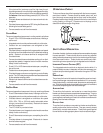
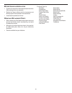
COMFORTNET C OMPATIBLE F URNACE WITH N ON-COMFORTNET
COMPATIBLE
S INGLE-STAGE A IR CONDITIONER
Four wires are required between the furnace and thermostat. Two
wires are required between the furnace control and single stage air
conditioner. For this system configuration, the “Y1” terminal on
the integrated furnace control becomes an output rather than an
input. The “Y1” connection to the outdoor unit is made using both
4-position thermostat connectors in the CTK0*AA kit. Remove
the red keying tabs from the on-board connector block and posi-
tion both 4-position connector such that “1”, “2”, “R”, “C”, and “Y1”
positions are filled.
12RC
C Y
ComfortNet Compatible
Furnace Integrated
Control Module
CTK0*A
A
Thermostat
Non-ComfortNet Compatible
Single Stage AC
G
W1 W2 Y1 Y2
O
12RC
4-Position Connectors
from CTK0*AA
Thermostat Kit
System Wiring between Furnace and Non-Communicating
Compatible Single Stage Air Conditioner
COMFORTNET™ SYSTEM A DVANCED F EATURES
The ComfortNet system permits access to additional system in-
formation, advanced setup features, and advanced diagnostic/
troubleshooting features. These advanced features are organized
into a menu structure. The menus are accessed and navigated as
described in the instructions provided with the CTK0*AA com-
municating control.