


38
ATMOSPHERE
PORT
DIRECTION
FLOW
PS
CONNECTION
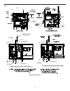
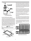
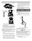
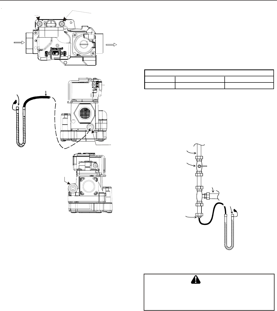
Honeywell Model VR9205R
Outlet
Pressure
Tap
1/8 NPT
Inlet
Pressure
Tap
1/8 NPT
2-PIN
POWER
CONNECTOR
i
M
a
n
o
m
e
t
e
r
M
a
n
o
m
e
t
e
r
H
o
s
e
O
p
e
n
t
o
A
t
m
o
s
p
h
e
r
e
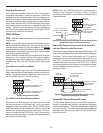
Honeywell Model VR9205R Connected to Manometer
1. Turn OFF gas to furnace at the manual gas shutoff valve
external to the furnace.
2. Connect a calibrated water manometer (or appropriate gas
pressure gauge) at either the gas valve inlet pressure boss
or the gas piping drip leg. See Honeywell VR9205R gas
valve figure for location of inlet pressure boss.
NOTE: If measuring gas pressure at the drip leg or Honeywell
VR9205R gas valve, a field-supplied hose barb fitting must be
installed prior to making the hose connection.
3. Turn ON the gas supply and operate the furnace and all
other gas consuming appliances on the same gas
supply line.
Field Test Mode is intended to help a service person
troubleshoot and check out an installed appliance.
To enter Field Test Mode the Fault Recall Push-Button
must be pressed twice within a 5 second period at any
time during a heating cycle, at which time the display
will show “Ft”. While the display is showing “Ft”,
pressing and holding the Fault Recall Push-Button for
3 seconds will enable the field test mode and override
the normal firing rate sequence at a rate of 100% for 5
minutes or until the end of the call for heat. The display
will show the normal “Hi” while the control is firing at
100%. If the Fault Recall Push-Button has not been
pressed within 5 seconds of displaying “Ft” the display
will revert back to normal.
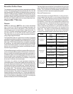
4. Measure furnace gas supply pressure with burners firing.
Supply pressure must be within the range specified in the
Inlet Gas Supply Pressure table.
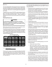
Natural Gas
Minimum: 5.0" w.c. Maximum:10.0" w.c.
Propane Gas
Minimum: 11.0" w.c. Maximum:13.0" w.c.
Inlet Gas Supply Pressure
If supply pressure differs from table, make the necessary adjust-
ments to pressure regulator, gas piping size, etc., and/or consult
with local gas utility.
5. Turn OFF gas to furnace at the manual shutoff valve and
disconnect manometer. Reinstall plug before turning on
gas to furnace.
6. Turn OFF any unnecessary gas appliances stated in step
3.
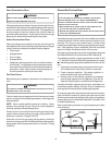
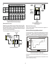
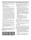
Gas Line
Gas
Shutoff
Valve
Gas Line
To Furnace
Drip Leg Cap
With Fitting
Manometer Hose
Manometer
Open To
Atmosphere
Measuring Inlet Gas Pressure (Alt. Method)
GAS MANIFOLD P RESSURE MEASUREMENT
T
O
PREVEN T
UNRELIABLE
OPE RATION
OR
EQUIPMENT
DAMAGE
,
THE
GAS
MANIFOLD
PRESSURE
MUST
BE
AS
SPECIFIED
ON
THE
UNIT
RATING
PLATE
.G
AS
VALVE
IS
FACTORY
SET
AND
DOES
NOT
REQ UIRE
ANY
F
IELD
ADJUSTMENT
.D
O
NOT
ATTEMP T
TO
ADJUST
VALVE
.
CAUTION
The manifold pressure must be measured with the burners operat-
ing. To measure the manifold pressure, use the following proce-
dure.
1. Turn OFF gas to furnace at the manual gas shutoff valve
external to the furnace.
2. Turn off all electrical power to the system.