


11
Horizontal Furnace
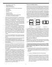
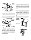
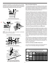
FURNACE SUSPENSION
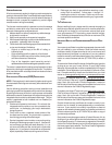
If suspending the furnace from rafters or joists, use 3/8" threaded
rod and 2”x2”x1/8” angle iron as shown in the following diagram.
The length of rod will depend on the application and the clearances
necessary.
If the furnace is installed in a crawl space it must be suspended
from the floor joist or supported by a concrete pad. Never install
the furnace on the ground or allow it to be exposed to water.
2" 2" 3/8"
ANGLE
IRON
(3
PLACES
)
XX
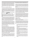
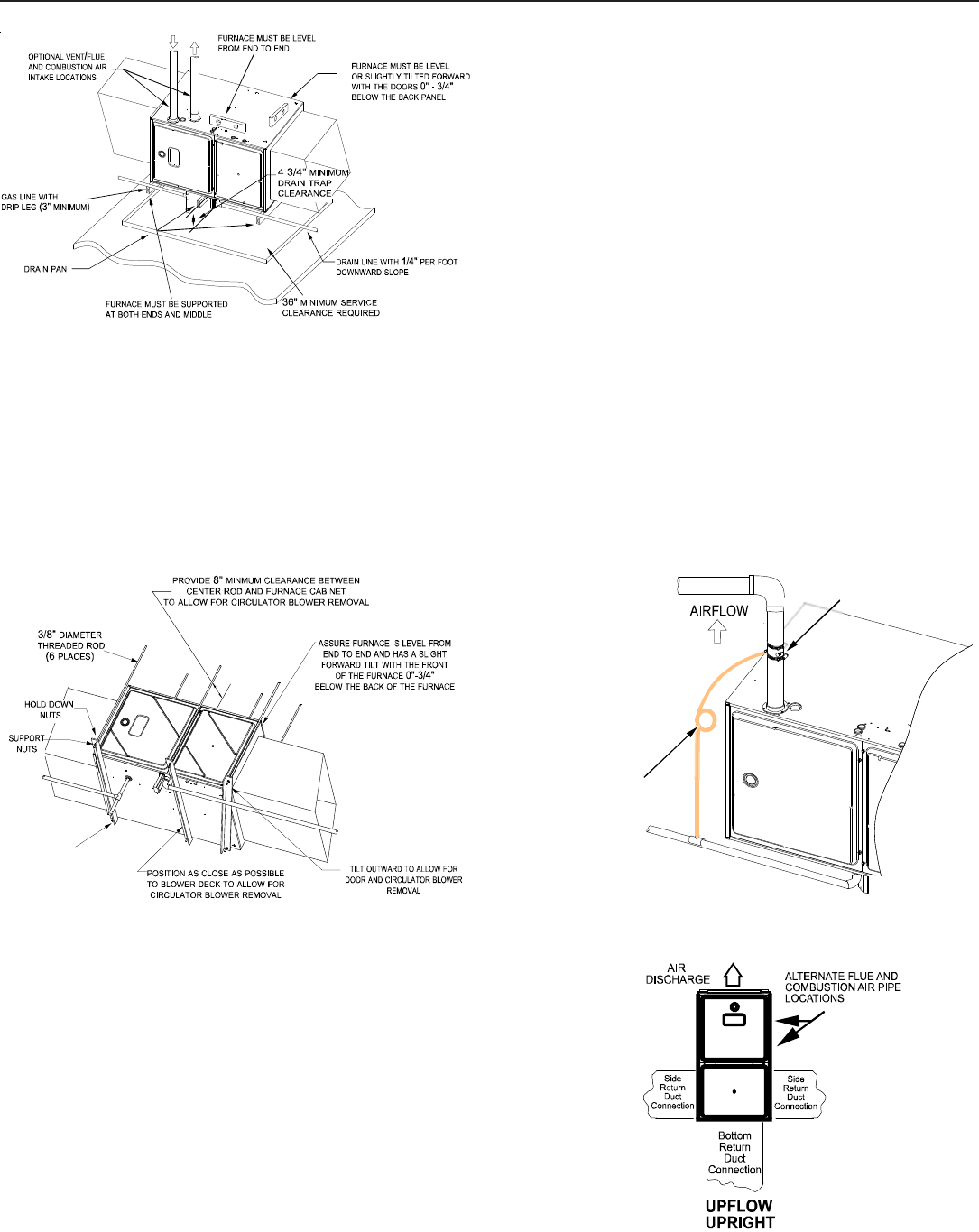
DRAIN T RAP AND LINES
In horizontal applications the condensate drain trap is secured to
the furnace side panel, suspending it below the furnace. A mini-
mum clearance of 4 3/4 inches below the furnace must be pro-
vided for the drain trap. Additionally, the appropriate downward
piping slope must be maintained from the drain trap to the drain
location. Refer to Condensate Drain Trap and Lines for further de-
tails. If the drain trap and drain line will be exposed to temperatures
near or below freezing, adequate measures must be taken to pre-
vent condensate from freezing.
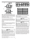
LEVELING
Leveling ensures proper condensate drainage from the heat ex-
changer and induced draft blower. For proper flue pipe drainage,
the furnace must be level lengthwise from end to end. The furnace
should also be level from back to front or have a slight tilt with the
access doors downhill (approximately 3/4 inches) from the back
panel. The slight tilt allows the heat exchanger condensate, gen-
erated in the recuperator coil, to flow forward to the recuperator coil
front cover.
ALTERNATE V ENT/FLUE AND C OMBUSTION A IR C ONNECTIONS
In horizontal installations provisions for alternate flue and combus-
tion air piping are available for upflow furnaces with left discharge
and counterflow furnaces with right air discharge. This configura-
tion allows the flue and combustion air piping to be run vertically
through the side of the furnace. Refer to the “Recommended In-
stallation Positions” figure for further detail. The standard piping
connections may also be used in these positions. Refer to Vent/
Flue Pipe and Combustion Air Pipe for details concerning the
conversion to the alternate vent/flue and combustion air connec-
tions.
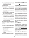
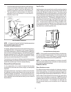
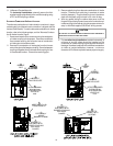
When using the horizontal alternate vent configuration, you must
use the RF000142 vent drain kit. See following illustration.
NOTE:
MAKE SMALL
LOOP IN HOSE TO
SERVE AS “P-TRAP”
VENT-DRAIN
“FIELD-SUPPLIED DRAIN
HOSE”
“FIELD-
SUPPLIED CONNECTOR”
FROM VENT-
DRAIN CONNECTED TO
CONDENSATE DRAIN
LINE WITH
Alternate Vent/Flue Location