


27
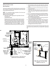
To ensure proper unit grounding, the ground wire should run from
the furnace ground screw located inside the furnace junction box
all the way back to the electrical panel. NOTE: Do not use gas
piping as an electrical ground. To confirm proper unit grounding,
turn off the electrical power and perform the following check.
1. Measure resistance between the neutral (white) connection
and one of the burners.
2. Resistance should measure 10 ohms or less.
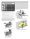
This furnace is equipped with a blower door interlock switch which
interrupts unit voltage when the blower door is opened for servicing.
Do not defeat this switch.
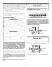
24 VOLT T HERMOSTAT W IRING
W
IRE
ROUTING
MUST
NOT
INTERFERE
WITH
CIRCULATOR
BLOWE R
OPE RATION
,
FILTER
REMOVAL
OR
ROUTINE
MAINTENANCE
.
A
REMOVABLE
PLUG
CONNECTOR
IS
PROVIDED
WITH
THE
CON TROL
TO
MAKE
THERMOSTAT
WIRE
CONNECTIONS
.T
HIS
PLUG
MAY
BE
REMOVED
,
WIRE
CONNECTIONS
MADE
TO
THE
PLUG
,
AND
REPLACED
.I
T
IS
RECOMMEN DED
THAT
MULTIPLE
WIRES
INTO
A
SINGLE
TERMINAL
BE
TWISTED
TOGETHER
PRIO R
TO
INSERTING
INTO
THE
PLUG
CONNECTOR
.F
AILURE
TO
DO
SO
MAY
RESULT
IN
INTERMITTENT
OPE RATION
.
STRONGLY
IMPORTANT NOTE
D
IP
SWITCH
#13MUST
BE
SET
TO
MATCH
THERMOSTAT
TYPE
.T
OSE
THE
CTK01AA
COMMUNICATING
THERMOSTAT
,
DIP
SWITCH
#13
MUST
BE
SET
TO
ON
POSITION
.T
HIS
IS
ALSO
THE
CORRECT
SETTING
FOR
A
NON
‐
COMMUNICATING
2‐
STA GE
THERMOSTAT
.T
O
USE
CTK02AA
MODULAT ING
THERMOSTAT
,
CHECK
TO
MAKE
SURE
DIP
SWITCH
#13
IS
IN
THE
OFF
POSITION
(
FACTORY
POSITION
).T
HIS
IS
ALSO
THE
CORR ECT
POSITION
WHEN
USING
A
NON
‐
COMMUNICATING
SINGLE
‐
STA GE
THERMOSTAT
.
U
IMPORTANT NOTE
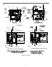
As a two-stage non-communicating furnace, the furnace integrated
control module provides terminals for both “W1” and “W2”, and
“Y1” and “Y2” thermostat connections. This allows the furnace to
support the following system applications: ‘Two-Stage Heating
Only’, ‘Two-Stage Heating with Single Stage Cooling’, and ‘Two-
Stage Heating with Two-Stage Cooling’. Refer to the following fig-
ures for proper connections to the integrated control module.
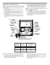
Low voltage connections can be made through either the right or
left side panel. Thermostat wiring entrance holes are located in the
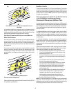
blower compartment. The following figure shows connections for a
“heat/cool system”.
This furnace is equipped with a 40 VA transformer to facilitate use
with most cooling equipment. Consult the wiring diagram, located
on the blower compartment door, for further details of 115 Volt and
24 Volt wiring.
NOTE: Use of ramping profiles requires a jumper between Y1
and O.
T
HERMOSTAT
“R”
REQUIRED
IF
OUTDOOR
UNIT
IS
EQUIPPED
WITH
A
C
OMFORT
A
LERT
™
MODULE
OR
IF
THE
OUTDOOR
UNIT
IS
A
PART
OF
THE
C
ONFORT
N
ET
™
FAMILY
OF
EQUIPMENT
.
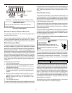
IMPORTANT NOTE
AUX
DEHUM
W2
C
1
Y1
2
R
W1
Y2
G
O
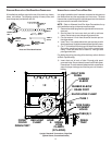
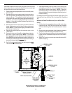
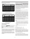
24 V THERMOSTAT CONNECTIONS
Low Voltage Connections with Auxiliary Terminals
The auxiliary contacts are shipped with a factory installed
jumper. As an option, the auxiliary contacts may be wired to
a normally closed float switch. In the event of open contacts,
the furnace will be disabled until the condition is corrected.
These are 24 volt terminals fed internally, do not apply another
voltage source to these terminals.
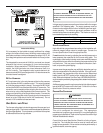
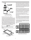
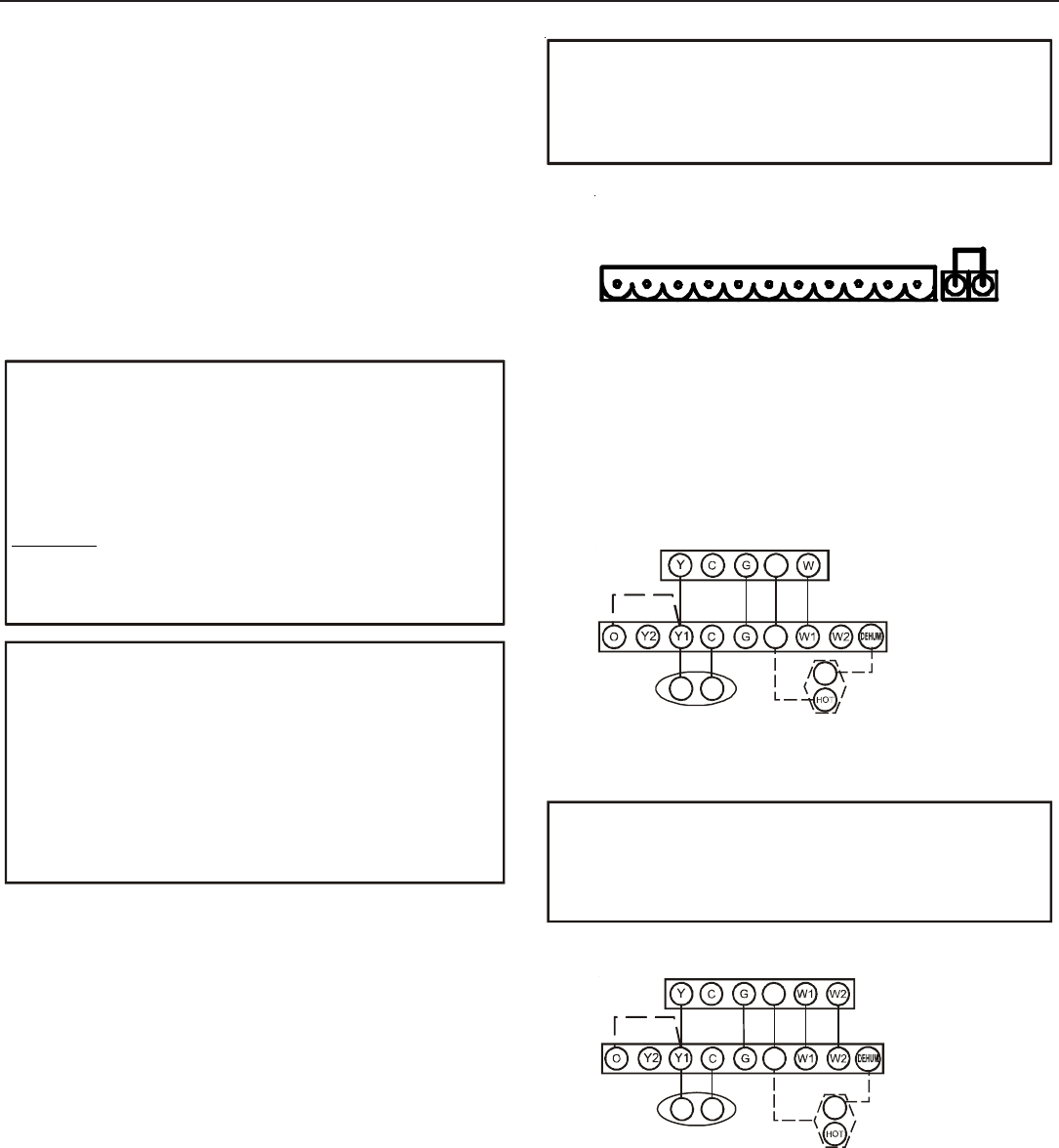
R
Y C
NEU
Furnace Integrated
Control Module
Remote
Condensing Unit
(Single-Stage Cooling)
Dehumidistat
[Optional]
R
Thermostat - Single-Stage Heating with Single-Stage Cooling
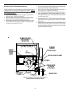
T
O
APPLY
A
SINGLE
‐
STA GE
H
EATING
T
HERMOSTAT
,
THE
THERMOSTAT
SELECTOR
SWITCH
ON
THE
I
NTEGRATE D
C
ONTROL
M
ODULE
MUST
BE
SET
ON
SINGLE
‐
STAGE
.
IMPORTANT NOTE
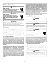
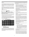
_____________________________________
R
Y C
Furnace Integrated
Control Module
Remote
Condensing Unit
(Single-Stage Cooling)
Dehumidistat
[Optional]
NEU
R
Thermostat - Two-Stage Heating with Single-Stage Cooling