


39
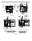
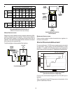
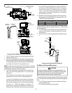
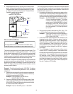
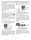
3. Outlet pressure tap connections: Remove the outlet
pressure boss plug. Install an 1/8" NPT hose barb fitting
into the outlet pressure tap.
4. Attach a hose and manometer to the outlet pressure barb
fitting.
5. Turn ON the gas supply.
6. Turn on power and close thermostat “R” and “W1” contacts
to provide a call for low stage heat.
NOTE: After every time the main power is turned off
and back on, the furnace will enter a calibration routine
on the next call for heat The inducer will ramp up and
down during the calibration routine. After calibration,
the furnace will proceed to ignition cycle.
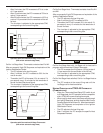
7. Field Test Mode is intended to help a service person
troubleshoot and check out an installed appliance.
To enter Field Test Mode the Fault Recall Push-Button
must be pressed twice within a 5 second period at any
time during a heating cycle, at which time the display
will show “Ft”. While the display is showing “Ft”,
pressing and holding the Fault Recall Push-Button for
3 seconds will enable the field test mode and override
the normal firing rate sequence at a rate of 100% for 5
minutes or until the end of the call for heat. The display
will show the normal “Hi” while the control is firing at
100%. If the Fault Recall Push-Button has not been
pressed within 5 seconds of displaying “Ft” the display
will revert back to normal.
NOTE: Gas valve is factory set and does NOT require
any field adjustment. Do NOT attempt to adjust valve.
Measure the gas manifold pressure with burners firing.
8. Turn off all electrical power and gas supply to the system.
9. Remove the manometer hose from the hose barb fitting.
10. Remove the 1/8" NPT hose barb fitting from the outlet
pressure tap. Replace the outlet pressure boss plug and
seal with a high quality thread sealer.
11. Turn on electrical power and gas supply to the system.
12. Close thermostat contacts “R” and “W1/W2” to energize
the valve.
Using a leak detection solution or soap suds, check for leaks at
outlet pressure boss plug. Bubbles forming indicate a leak. SHUT
OFF GAS AND REPAIR ALL LEAKS IMMEDIATELY!
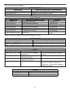
NOTE: For natural gas to LP conversion, consult the furnace
Specification Sheet.
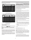
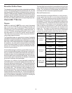
Range Nominal
Natural High Stage 3.2 - 3.8" w.c. 3.5" w.c.
Propane High Stage 9.5 - 10.5" w.c. 10.0" w.c.
Manifold Gas Pressure
Gas
GAS I NPUT R ATE M EASUREMENT (NATURAL G AS O NLY)
The gas input rate to the furnace must never be greater than that
specified on the unit rating plate. To measure natural gas input
using the gas meter, use the following procedure.
1. Turn OFF the gas supply to all other gas-burning appliances
except the furnace.
2. While the furnace is operating, time and record one
complete revolution of the smallest gas meter dial.
3. Calculate the number of seconds per cubic foot (sec/ft
3
) of
gas being delivered to the furnace. If the dial is a one cubic
foot dial, divide the number of seconds recorded in step 2
by one. If the dial is a two cubic foot dial, divide the number
of seconds recorded in step 2 by two.
4. Calculate the furnace input in BTUs per hour (BTU/hr). Input
equals the sum of the installation’s gas heating value and a
conversion factor (hours to seconds) divided by the number
of seconds per cubic foot. The measured input must not
be greater than the input indicated on the unit rating plate.
EXAMPLE:
Installation’s gas heating (HTG) value: 1,000 BTU/ft
3
(Obtained from gas supplier)
Installation’s seconds per cubic foot: 34 sec/ ft
3
Conversion Factor (hours to seconds): 3600 sec/hr
Input = (Htg. value x 3600) ÷ seconds per cubic foot
Input = (1,000 BTU/ft
3
x 3600 sec/hr) ÷ 34 sec/ ft
3
Input = 106,000 BTU/hr
NOTE: The final manifold pressure cannot vary by more than ±
0.3” w.c. for Natural and + 0.5” for LP from the specified setting.
Consult your local gas supplier if additional input rate adjustment
is required.
5. Turn ON gas to and relight all other appliances turned off in
step 1. Be certain that all appliances are functioning properly
and that all pilot burners are operating.
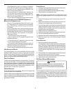
TEMPERATURE R ISE
Temperature rise must be within the range specified on the unit
rating plate. An incorrect temperature rise may result in condens-
ing in or overheating of the heat exchanger. An airflow and tem-
perature rise table is provided in the Specification Sheet applicable
to your model. Determine and adjust temperature rise as follows:
1. Operate furnace with burners firing for approximately ten
minutes. Ensure all registers are open and all duct dampers
are in their final (fully or partially open) position.
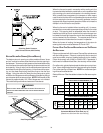
2. Place thermometers in the return and supply ducts as close
to the furnace as possible. Thermometers must not be
influenced by radiant heat by being able to “see” the heat
exchanger.
3. Subtract the return air temperature from the supply air
temperature to determine the air temperature rise. Allow
adequate time for thermometer readings to stabilize.