


48
FAULT C LEAR SEQUENCE:
• Only allowed in standby mode, while display is
showing ON.
• Hold fault recall push-button for 5-10 seconds (until
display starts flashing “—”) and then release.
• All faults in the history will have been cleared, and
display returns to ON.
• If you hold the button for longer than 10 seconds, the
display will return to ON and the faults will not be
cleared.
N
ORMAL
S
EQUENCE
OF
O
PERATION
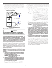
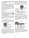
POWER U P
The normal power up sequence is as follows:
• 115 VAC power applied to furnace.
• Integrated control module performs internal checks.
• Integrated control module monitors safety circuits
continuously.
• Furnace awaits call from thermostat. Dual 7-segment LED’s
display
OO
OO
O while awaiting call from thermostat.
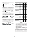
HEATING M ODE
The normal operational sequence in heating mode is as follows:
• Thermostat contacts close, initiating a call for heat.
• Integrated control module performs safety circuit checks.
• Induced draft blower is energized on high speed for a 15-
second prepurge.
• Induced draft blower steps to low speed following prepurge.
Low stage pressure switch contacts are closed.
• Igniter warm up begins upon step to low speed and
presence of closed low stage pressure switch contacts.
• Gas valve opens at end of igniter warm up period, delivering
gas to burners and establishing flame.
• Integrated control module monitors flame presence. Gas
valve will remain open only if flame is detected.
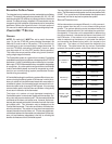
• The percentage of heating demand is sent from the IFC
to determine what RPM the draft inducer should run at.
A higher percentage demand will drive the inducer RPM
higher. This will cause the gas valve to modulate higher.
The burner will modulate based on the inducer speed
• Circulator blower is energized on heat speed following a
thirty (30) second blower on delay. The circulator blower
CFM will increase or decrease with gas valve modulation.
Electronic air cleaner terminal is energized with circulator
blower.
• Furnace is now operating on the specified stage called for
by the thermostat.
• Furnace runs, integrated control module monitors safety
circuits continuously.
• If the two-stage thermostat changes the call from low heat
to high heat, the integrated control module will immediately
switch the induced draft blower, gas valve, and circulator
blower to their high stage settings.
• The thermostat contacts open, completing the call for heat.
• Gas valve closes, extinguishing flame.
• Induced draft blower is de-energized following a fifteen second
post purge. Humidifier contacts open.
• Circulator blower continues running for the selected heat
off delay period (90, 120, 150 or 180 seconds). The speed
run during this period depends on the last heat call provided
by the thermostat.
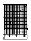
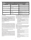
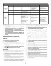
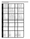
LED LED Status Indication Possible Causes Corrective Action(s) Notes & Cautions
Off • Normal condition • None • None • None
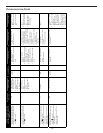
• Depress once quickly for a
p
ower-u
p
reset
• Depress and hold for 2
seconds for an out-of-box
reset.
• Control power up
• Learn button depressed
Rapid Flashing • Normal network traffic • Control is “talking” on
network as expected
• None • None
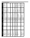
• Data 1 and data 2 wires reversed
at furnace, thermostat or
communicating compatible
outdoor AC/HP
• Check communications
wiring (data 1/ data 2
wires).
• Turn power OFF prior to
repair.
• Short between data 1 and
data 2 wires.
• Check wire connections at
terminal block
• Verify wires at terminal
blocks are securely twisted
together prior to inserting
into terminal block.
• Short between data 1 or
data 2 wires and R
(24VAC) or C (24VAC
common).
• Check data 1/ data 2
voltages.
• Verify data 1 and data
voltages as described above
• Communications Failure • Communications Failure
• None
• Depress Learn Button
• Verify that pull up, pull
down and bias dip
switches are in the
ON position.
Green
Receive
LED
2 Flashes • Out-of-box reset • None
On Solid • Data 1/ Data 2 miss-wire
Red
Communications
LED
1 Flash