38
221834B
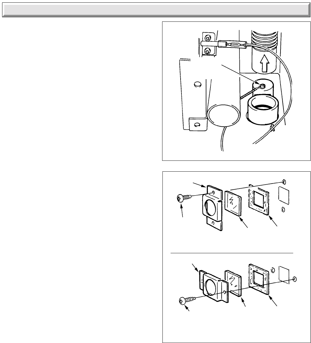
Diagram 14.13
Diagram 14.14
VIEWING WINDOW/INNER CASE
FRAME
VIEWING WINDOW/COMBUSTION
CHAMBER FRONT PANEL
FRAME
GLASS
GASKET
CONDENSATE
SENSOR
SCREW
SECURING
SCREW (2)
GLASS
GASKET
SECURING
SCREW (2)
14 Replacement of Parts
14.12 Insulation - Rear - diagram 14.10
With the heat exchangers and burner assembly removed, as
Sections 14.10 and 14.11, the rear insulation pad can be
removed as shown.
14.13 Insulation: Combustion Chamber Front
Panel: diagram 14.11
Remove the two screws from the viewing window then slide the
insulation pad out.
14.14 Insulation - Sides - diagram 14.12
Remove the spark electrode refer to Section 12.4.
Remove the insulation by sliding it out.
14.15 Condensate Sensor: diagram 14.13
Refer to the relevant parts of Section 14.2 to remove the screw.
14.16 Viewing Window Glass: diagram 14.14
Remove the two screws to release the frame and glass.
When replacing take care not to damage the gasket.
14.17 Inner Case Cover Seal
When removing seal make sure that all the old adhesive is
removed.
When fitting the new seal make sure that it fits correctly and has
not buckled.
14.18 Fascia and Lights Assembly
Release the control box as Section 9.
Refer to the relevant parts of Section 14.5 to remove the fascia
and lights bracket.


