


10
221834B
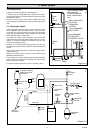
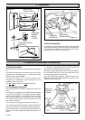
Diagram 2.5
METHOD 1
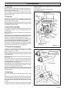
METHOD 2
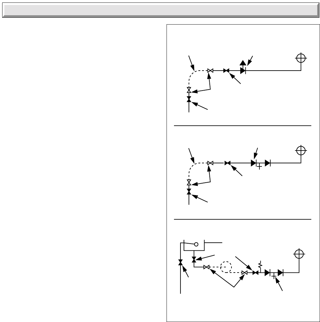
METHOD 3
SUPPLY STOP
VALVE
SUPPLY
PIPE
HOSE
UNIONS
SERVICING
VALVE
TEMPORARY
HOSE
HEATING
SYSTEM
HEATING
SYSTEM
TEMPORARY
HOSE
HOSE
UNIONS
SERVICING
VALVE
SUPPLY
PIPE
SUPPLY STOP
VALVE
DOUBLE CHECK
VALVE ASSEMBLY
HEATING
SYSTEM
SERVICING
VALVE
SUPPLY
STOP VALVE
SUPPLY
PIPE
HOSE
UNIONS
DOUBLE CHECK
VALVE ASSEMBLY
OVERFLOW
CISTERN
COMBINED
CHECK VALVE
AND VACUUM
BREAKER
PRESSURE
REDUCING
VALVE
0051
M
2 Water Sytem
2.12 Pressure Gauge
A pressure gauge with a set pointer and covering at least 0 to
4bar (0 to 60lb/in
2
) shall be fitted permanently to the system is
a position where it can be seen when filling the system.
2.13 Domestic Hot Water Cylinder
SINGLE FEED INDIRECT CYLINDERS ARE NOT SUITABLE.
The hot water cylinder must be of the indirect coil type. It must
be suitable for working at a gauge pressure of 0.35bar above
the safety valve setting.
2.14 Water Makeup
Provision should be made for replacing water loss from the
system using a make up bottle or filling loop mounted in a
position higher than the top point of the system, connected
through a non-return valve to the return side of either the
heating circuit or the hot water cylinder.
Alternatively, provision for make up can be made using a filling
loop.
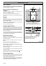
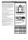
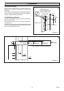
2.15 Filling a Sealed Water System
Provision for filling the system at low level must be made. Three
methods are shown in diagram 2.5. There must be no permanent
connection to the mains water supply, even through a non-
return valve.