


37
221834B
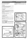
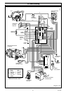
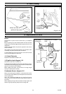
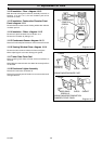
Diagram 14.9
UNION
CONNECTION
PRIMARY
HEAT
EXCHANGER
UNION
CONNECTION
BURNER
SECONDARY HEAT
EXCHANGER
UNION
CONNECTION
14 Replacement of Parts
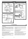
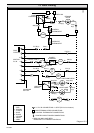
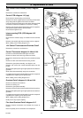
Heat Exchanger - Primary - diagram 14.10
Disconnect the three union connections.
14.11 Burner: diagram 14.9
Note: To carryout the following operations it will be found more
convenient if the whole of the heat exchanger and burner are
removed as a unit.
Follow the relevant parts of Servicing Section and remove the
bypass heat shield, fan/flue hood, combustion chamber front
panel, heat exchanger baffle, spark electrode, injector and
thermostat phials.
Release the flexible tube from the condense drain trap, this is
a push-fit.
Release union connections and the six securing screws, then
remove the complete assembly.
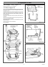
Remove the insulation as Section 14.14 and retain for use in the
replacement part.
Disconnect the two union connections.
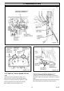
Fit the insulation.
Diagram 14.10
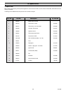
Diagram 14.11
INSULATION
SECURING
SCREW (2)
REAR
INSULATION
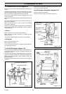
COMBUSTION
CHAMBER
FRONT PANEL
PILOT
VIEWING
WINDOW
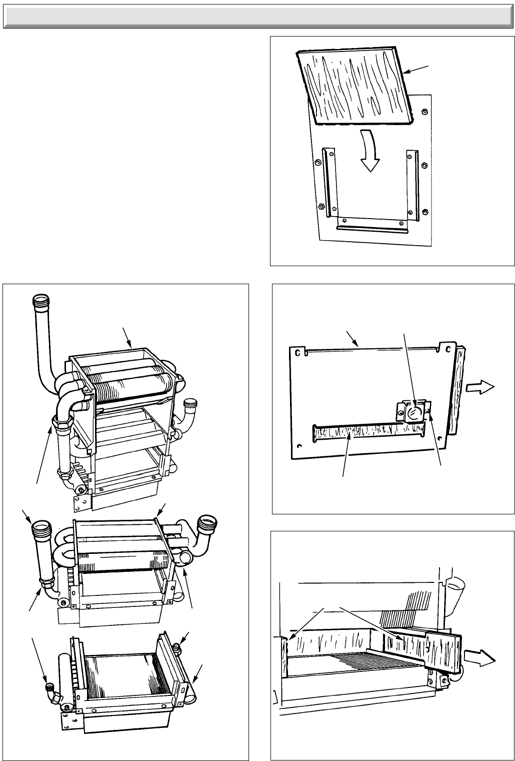
Diagram 14.12
SIDE INSULATION