33
221834B
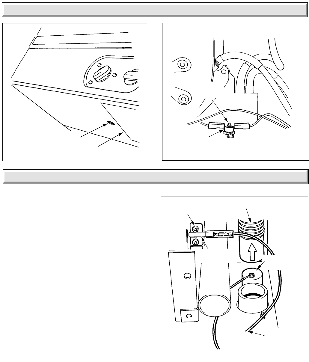
Diagram 13.4
Diagram 13.5
4067 S
INSTRUCTION LABEL
RESET BUTTON
7891
FLUE HOOD
OVERHEAT
THERMOSTAT
RESET
BUTTON
13 Fault Finding
Notes:
Replacement of parts must be carried out by a competent
person.
Before replacing any parts isolate the boiler from the electrical
supply and turn the gas supply off at the gas service cock, see
diagram 8.1.
Unless stated otherwise, all parts are replaced in the reverse
order to removal.
After replacing any parts always test for gas soundness and if
necessary carry out functional check of controls.
For the following the front case and inner case cover will need
to be removed, diagrams 5.2 and 5.3.
14.1 Spark Electrode
Replace as described in Section 12.4.
14.2 Ignition Lead: diagram 14.2
Release the control box as Section 9.
To disconnect the ignition lead from the control board, remove
the PCB from the mounting pegs, the front two have detachable
grips, the rear two are plain supports.
When refitting lead make sure that there is enough length
through the gland plate assembly.
Condensate Sensor: diagram 14.2
Refer to the relevant part of Section 14.2 to remove the screw.
The sensing screw is fitted to a push fit cap which can be levered
off for easy access.
Note. The condensate flexible tube is a push fit and can be
removed from the condensate drain trap to improve access to
the screw.
When replacing the cap make sure that it is firmly in place and
that the ring tag is pointing away from the casing side.
Diagram 14.2
IGNITION
SENSING
LEAD
5549
SECURING
SCREW (2)
CONDENSATE FLEXIBLE
TUBE
SPARK
ELECTRODE
CONDENSATE
DRAIN CAP
14 Replacement of Parts


