


16
221834B
OLIVE
FLOW
RETURN
28mm O.D.
COPPER
TUBING
WATER CONNECTIONS
FLUE GAS
SAMPLE
POINT
UNION NUT
4037
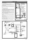
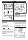
6 Water and Condensate Connections
It is, therefore, recommended that any external condensate
drain pipe is insulated to prevent it freezing up.
Alternatively, a larger diameter pipe can be used and insulated.
The condensate drain pipe should be checked during any
servicing and any debris found removed.
Refer to the British Gas publication “Guidance Notes for the
Installation of Domestic Condensing Boiler” for advice on the
disposal of boiler condensate.
Diagram 6.1
0170
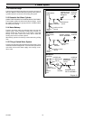
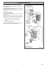
Diagram 5.7
4043 S
CLEAR
TUBES
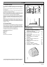
ELECTRICAL
CONNECTIONS
SECURING
SCREWS (3)
RED TUBE
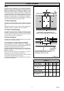
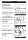
Diagram 5.6
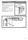
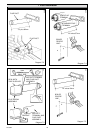
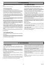
TEMPLATE
BOILER TOP
FIXING POINTS
7dia.
7dia.
3/16dia. PLUG
NO.
12x2in.
NO.
12x2in.
BOILER MOUNTING
BRACKET
5mm
MOUNTING
BRACKET
FIXING
POINT(S)
3/16dia. PLUG
5 Preparation
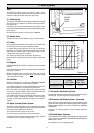
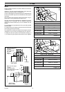
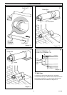
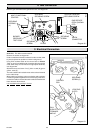
6 Water Connections
Make the water connection to the heating system, see diagram
6.1.
The boiler has compression connections with nuts and olives
supplied loose in the fittings pack, to accept 28mm outside
diameter copper tubing to BS2871.
The 28mm connections can be reduced to 22mm for the
Energysaver 40, provided the system resistance does not
exceed the chosen pump duty.
The right hand connection is the flow from the boiler.
6.1 Condensate Connection
The condensate drain connection is at the bottom right of the
boiler.
The drain ends in a spigot which is suitable for push fit 22mm
(
3
/
4
in) plastic overflow pipe, for example, Hepworth Polypipe,
Uponor, Osma, Orcaster. If using Marley, Terain or Hunter
tubing, which is slightly larger, use the silicone sealant provided
in the fittings pack to make a leak proof joint to the drain
connection on the boiler.
The condensate discharge pipe should have a fall of 2
1
/
2
o
.
It is not necessary to provide air breaks, or traps in the discharge
pipe since the boiler has an integral 50mm trap and siphon.
The boiler is fitted with a safety device to prevent the boiler from
working if the condensate pipe gets blocked by either ice or
debris.
AIR
PRESSURE
TUBES
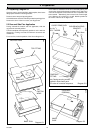
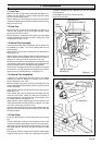
5.5 Boiler Preparation
Lift the boiler into position above the boiler mounting bracket,
lowering the boiler into position at the same time locating the
key hole slots of the boiler on to the securing screws, when
located secure the screws, see diagram 5.6.