21
221834B
✽
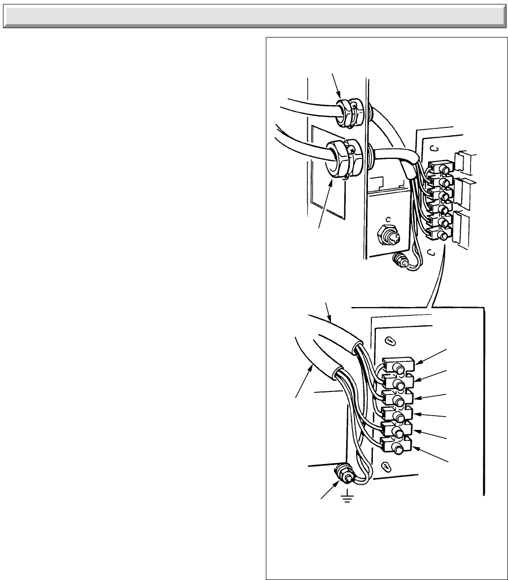
Diagram 9.2
✽RED LINK SL TO 1
REMOTE CONTROLS
SL
PL
PN
1
L
N
MAINS
SUPPLY
CABLE
PUMP CABLE
PUMP AND
REMOTE
CONTROLS
GROMMET
MAINS SUPPLY
CABLE GROMMET
CHASSIS
EARTH
POST
4052
9 Electrical Connection
9.1 Pump and External Controls Connection
The pump must be connected directly to the control box, as
shown in diagram 9.2.
Any external controls must only be connected to interrupt the
Red Link between terminals 1 and SL.
Thread the cable(s) through the large cable clamp in the side of
the control box.
9.2 Testing - Electrical
Checks to ensure electrical safety should be carried out by a
competent person.
In the event of an electrical fault after installation of the system,
preliminary electrical system checks as below should be carried
out:
1. Test insulation resistance to earth of mains cable.
2. Test the earth continuity and short circuit of all
cables.
3. Test the polarity of the mains.
The installer is requested to advise and give guidance to the
user of the controls scheme used with the boiler.


