


12
221834B
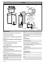
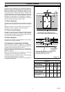
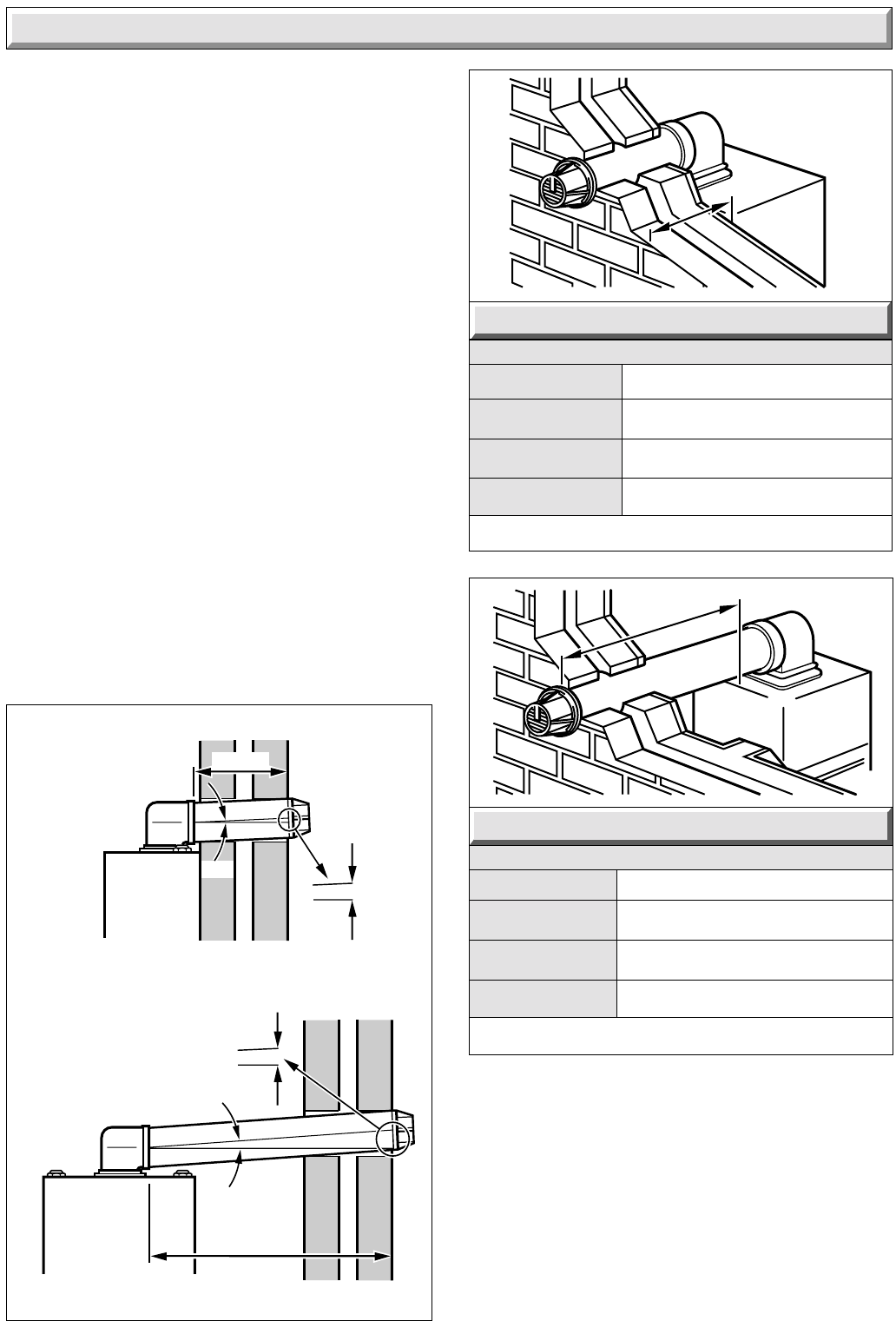
S = "External wall face" to "boiler casing"
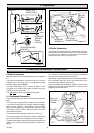
Diagram 4.3
REAR FLUE LENGTHS
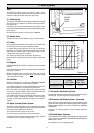
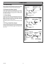
Diagram 4.1
SIDE FLUE LENGTHS
Diagram 4.2
0158M
2
˚
35mm
1metre
SIDE FLUE
FRONT VIEW
Make sure flue slopes
2
˚
down
towards the boiler
that is 35mm fall per metre
of flue length (2
˚
)
Make sure flue slopes
2
˚
down towards
the boiler
that is 35mm fall
per metre
of flue
length (2
˚
)
300mm
2
˚
10.5mm
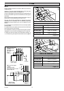
REAR FLUE
SIDE VIEW
R = Wall Thickness
STD Flue pack 80mm to 331mm
4 Flue
NOTE:
The flue must be installed in accordance with the current issue
of BS5440 Part 1.
Important. The flue must be installed with a fall of 35mm per
metre (2
o
) towards the boiler, see diagram 4.1.
It is of no advantage to exceed this angle (2
o
) indeed sealing of
the fan to flue elbow may become more difficult as the angle is
increased.
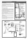
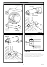
The air and flue duct connect to the top of the boiler using an
elbow which can be positioned to the side or rear.
The rear and side flue assemblies are designed for internal
installation, but if necessary, due to insufficient clearances
(boiler/flue terminal location) they can be installed from the
outside.
For a wall thickness up to 300mm the flue can be fully installed
from the inside.
For a wall thickness over 300mm the external cut hole will need
to be made good from the outside.
The standard flue is able to provide the duct lengths as shown
in diagram 4.2 for a rear flue and diagram 4.3 for a side flue.
If a longer flue duct is required, do not extend the ductings. A
1, 2 or 3metre long flue system and terminal can be supplied.
STD Flue pack
75mm to 442mm
3m Flue pack 75mm to 2933mm
2m Flue pack 75mm to 1953mm
3m Flue pack 80mm to 2821mm
2m Flue pack 80mm to 1841mm
1m Flue pack 75mm to 953mm
1m Flue pack 80mm to 841mm
'R'
'S'
6861
6860