


19
INSTALLATION INSTRUCTIONS
INSTALLATION
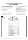
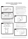
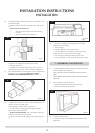
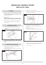
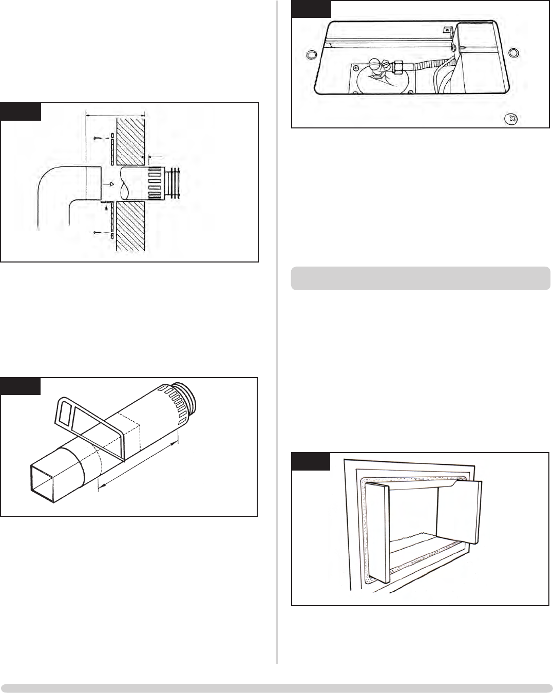
4.6 Onlythehorizontalterminalsectioncanbereducedinsize.
To find the length:
• Measurefromtheoutsideofthewalltothestoponthe
90°
• Add 10 mm to the outlet end
• Measurefromtheedgeoftheslotsclosestto
the wall
• Markaroundtheflue,Diagram20
20
10mm
AR0629
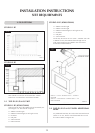
A wall plate is supplied to fix the flue to the wall:
• Bendthetabto90°
• Assembletheplateontothefluebutwaittosecureto
wall and flue after the flue is fully assembled, Diagram 19
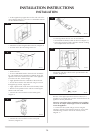
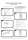
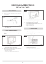
4.7 The cardboard fitment in the terminal is used to support the
flue whilst it is cut to length. ONCE CUT TO SIZE,
REMOVE THE CARDBOARD REMNANT, Diagram 21.
21
AR0630
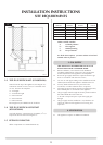
4.8 • Removethecompressionelbowfromtheapplianceand
connect it to the gas supply pipe.
As the appliance is fitted into the enclosure:
• Passtheelbowandsupplypipethroughthesilicone
panelontheLEFT-HANDside.
• PURGE THE SUPPLY PIPE. This is essential to expel any
debris that may block the gas controls.
• Connecttheelbowtotheapplianceinletpipe,Diagram
22.
22
AR1888
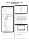
4.9 • Connectasuitablepressuregaugetothetestpoint
located on the inlet fitting
• Turnonthegas
• Lighttheapplianceandcheckforleaks.
• Turntheappliancetomaximumandcheckthatthe
supply pressure is as stated on the data badge.
• Turnoffthegasandreplacethetestpointscrew
• Turnthegasbackonandcheckthetestpointforleaks
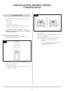
5. ASSEMBLING THE APPLIANCE
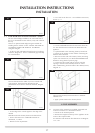
5.1 • Addthepebblesmakingsuretheyareflattenedsothey
are level with the rim of the tray
TAKECARENOTTOSPILLPEBBLESINTOTHEPILOT
AREA
ONLYPEBBLESSUPPLIEDBYGAZCOCANBEUSEDIN
THISFIRE
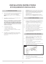
5.2 The back panel is already in place:
• Placethebottompanelatthebaseofthefire
• Slidethesidepanelsintoposition
23
AR1865
5.3 To fit the window frame:
• Keeptheframeintheuprightpositionwiththelocks
uppermost