


17
INSTALLATION INSTRUCTIONS
INSTALLATION
13
AR1905
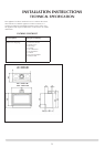
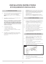
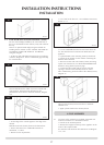
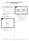
3.3 STUD WORK INSTALLATION METHOD 2 (EDGE)
Forthiscool-wallEdgeinstallation,theconvectedheatof
the fire is channelled into the chimney cavity and vented at
the top.
ThereisanoptionalStudioEdgeFixingKitavailablefor
installingthefirewithoutaframe.STUDIO1BFCODENo.
8727BFFK01STUDIO2BFCODENo.8727BFFK02
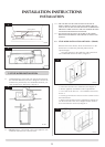
Using the fixing kit:
• Fitthetwosideandbottomchannelstothefrontflange
of the fire, Diagram 14. There is a deliberate gap at the top
for convected heat
14
AR1912
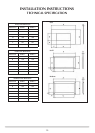
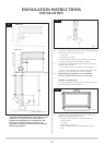
This now determines the width of your two vertical stud
work supports. The kit has been designed so that
plasterboard can be taken to the three channels, Diagram
14A
14a
AR1934
• Fixtheedgeoftheverticalsupporttotheedgeofthe
channel
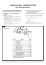
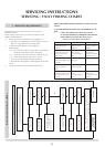
Build the stud work chimney breast to the desired size:
• Ensureallclearancestocombustiblematerialare
maintained, 3.1 above
• Decideonfluerequirements
• Cutaholefortheflueexit-seeInstallation Instructions,
Section 2, 2.5.
15
AR1902
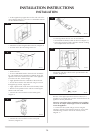
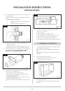
• Fitnon-combustibleboardtothestudworkabovethe
fire. This should extend a minimum of 400m above the
appliance.
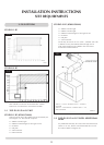
• Fitplasterboardtotheremainingchimneybreastfront
• Decideonthepositionforthewallboxcontainingthe
batteries and wall switch
• Mountitintothestudworkchimneybreastconnecting
up the wires from the fire, see Stud work Installation with
Frame for wiring detail on previous page
• Connectthefluesystemandgasservicesusingthe
opening in the side of the chimney breast for access.
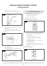
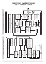
After commissioning, finish the sides of the chimney breast,
Diagram 16
16
AR1911
The top of the chimney breast must have a minimum
200mm
2
vent.
• Applyaplasterfinishtothechimneybreast
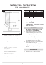
4. FLUE ASSEMBLY
4.1 Two types of flue terminals are available, horizontal and
vertical. To measure for a horizontal terminal:
• Decideontheterminalposition
• Measuretheheightfromthetopoftheappliancetothe
centre of the required outlet.
For minimum and maximum flue dimensions see Diagram
17A / 17B.