


18
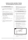
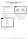
INSTALLATION INSTRUCTIONS
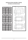
INSTALLATION
Studio 1 BF
17
Studio 2 BF
Studio 1 & 2 BF
AR1671, AR1971, AR1673
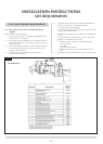
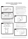
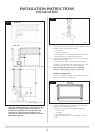
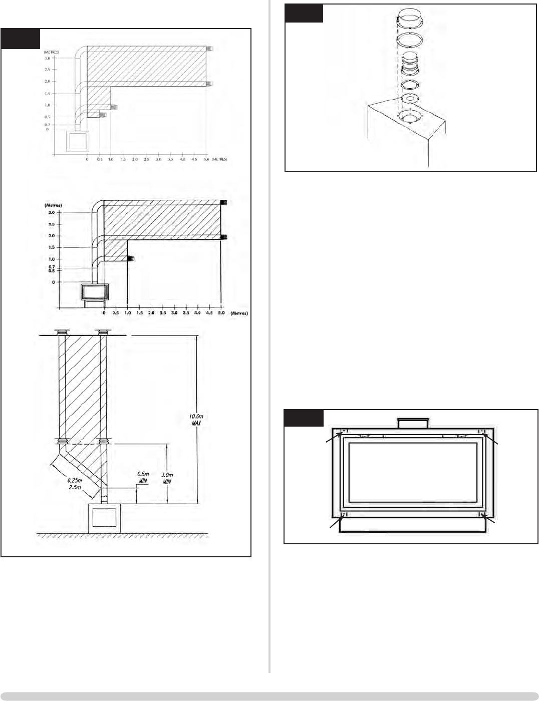
TAKE CARE WHEN MARKING OUT FOR THE FLUE AS IT
IS DIFFICULT TO MOVE AFTER INSTALLATION. IF A
RESTRICTOR IS REQUIRED FIT THIS BETWEEN THE
SMALL OUTLET SPIGOT AND THE AIR DUCT SEE
DIAGRAM 18. REFER TO TECHNICAL SPECIFICATIONS
FOR RESTRICTOR SIZE.
18
AR0627
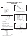
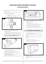
4.2 A 152mm (6") diameter hole in the wall is required to install
the flue. This can be achieved by either:
a) Core drill
b) Hammer and chisel
• Drillsmallholesaroundthecircumferencewhenusing
method b. Make good both ends of the hole.
4.3 • Removethebackingpaperfromthesiliconefoamstrip
supplied in the fixing kit
• Fixtothebackoftheouterflangesoftheappliance
• Ensureitislocatedbelowtheframelocationlugsonthe
top flange. Foam strip may need cutting to length.
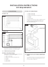
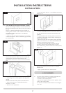
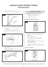
4.4 When installing the appliance into a combustible
enclosure, ensure all the clearances are observed.
METHOD 1 (FRAME) ONLY
• Securetheappliancethroughthefourfixingholesusing
the screws provided. See Diagram 19.
19
AR1914
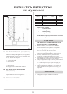
4.5 • Allowenoughroomeitheraboveortothesideofthe
appliance to assemble the flue on top
• Assembleahorizontalflueinthefollowingorder:
-Verticalsection
-90°elbow
-Horizontalplusterminal
• Supporttheopeningofamasonryinstallationwitha
lintel