


16
INSTALLATION INSTRUCTIONS
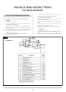
INSTALLATION
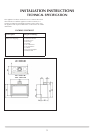
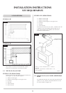
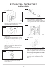
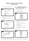
• Fitthesuppliedtopsupportbarintothestudworkatthe
correct height, Diagram 7, because no combustible material
can be used above the fire
7
AR1904
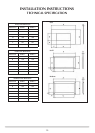
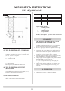
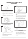
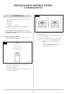
• Attachthe4framefixingbracketstothefire,Diagram8
• Fixfoamsealtotheouterflangeofthefire
8
AR1913
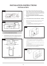
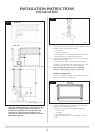
• Positionthefire
• Fitnon-combustibleboardtothestudworkaroundthe
fire. This should extend a minimum of 400mm above the
appliance and at least 50mm to the sides of the appliance
(from the outer box, not the flanges).
• Applyplasterboardtotheremainderofthestudwork
• Securethefirebacktothestudworkusingfourscrews
through flange, bracket, support bar
• Applyaplasterfinishtothefrontofthechimneybreast
• Decideonthepositionforthewallboxcontainingthe
batteries and wall switch
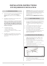
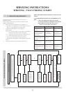
• Connectthewirefromthefiretothebatterypack,
Diagram 9
9
AR1920
• Connectthewirefromthefiretothetouchpad/
connector, Diagram 10
10
AR1919
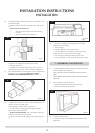
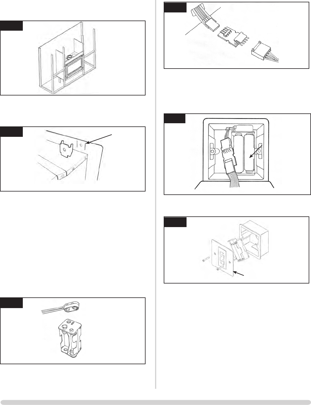
• CorrectlypositionthefournewAAsizebatteries
• Re-assemblethebatteryholderasshowninDiagram11
• Ensurethetouchpadcableistuckedtotheleftonfitting
the wall plate back onto the wall
11
AR1932
•Securethewallplatewiththetouchpadattachedtothe
wall box, Diagram 12
12
AR1887
wall plate
Because of the high temperatures this fire achieves, it is
advisable to use marble slips or similar material between the
appliance and the plasterboard
Never use a one-piece slip as expansion (even cracking)
can occur. If a slip is used, longer screws are needed to
secure the appliance.
• Connectthefluesystemandgasservicesusingthe
opening in the side of the chimney breast for access. After
commissioning, finish the sides of the chimney breast,
Diagram 13