


12
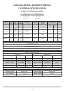
STUDIO 1 BF
1A
AR1671
STUDIO 2 BF
1A
AR1971
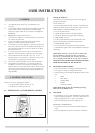
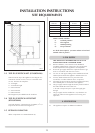
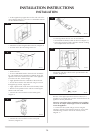
Start of bend to centre line of horizontal flue 170mm.
Centre line of vertical flue to end of bend 220mm.
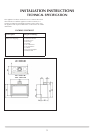
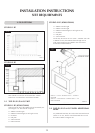
2.1 TOP FLUE UP & OUT KIT
STUDIO 1 BF (8534/8534AN)
Vertical from the top of the appliance then horizontally out.
(See Diagram 1A). The basic kit comprises:
1 x 200mm vertical length
1 x 500mm terminal length (cut to length on site)
1 x 90° elbow
1 x wall plate
1 x 70mm restrictor
1 x 60mm restrictor
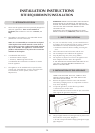
INSTALLATION INSTRUCTIONS
SITE REQUIREMENTS
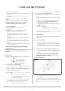
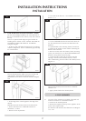
STUDIO 2 BF (8509/8509AN)
1 x 200mm vertical length
1 x 500mm vertical length
1 x 500mm terminal length (cut to length on site)
1 x 90° elbow
1 x wall plate
1 x 75mm restrictor
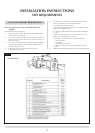
Thekitmaybeusedonitsown.(Note–STUDIO1BFwith
a 200mm rise only the 500mm terminal length can be
used).Extralengthsmaybeaddedtotheverticaland
horizontal from the list below.
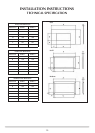
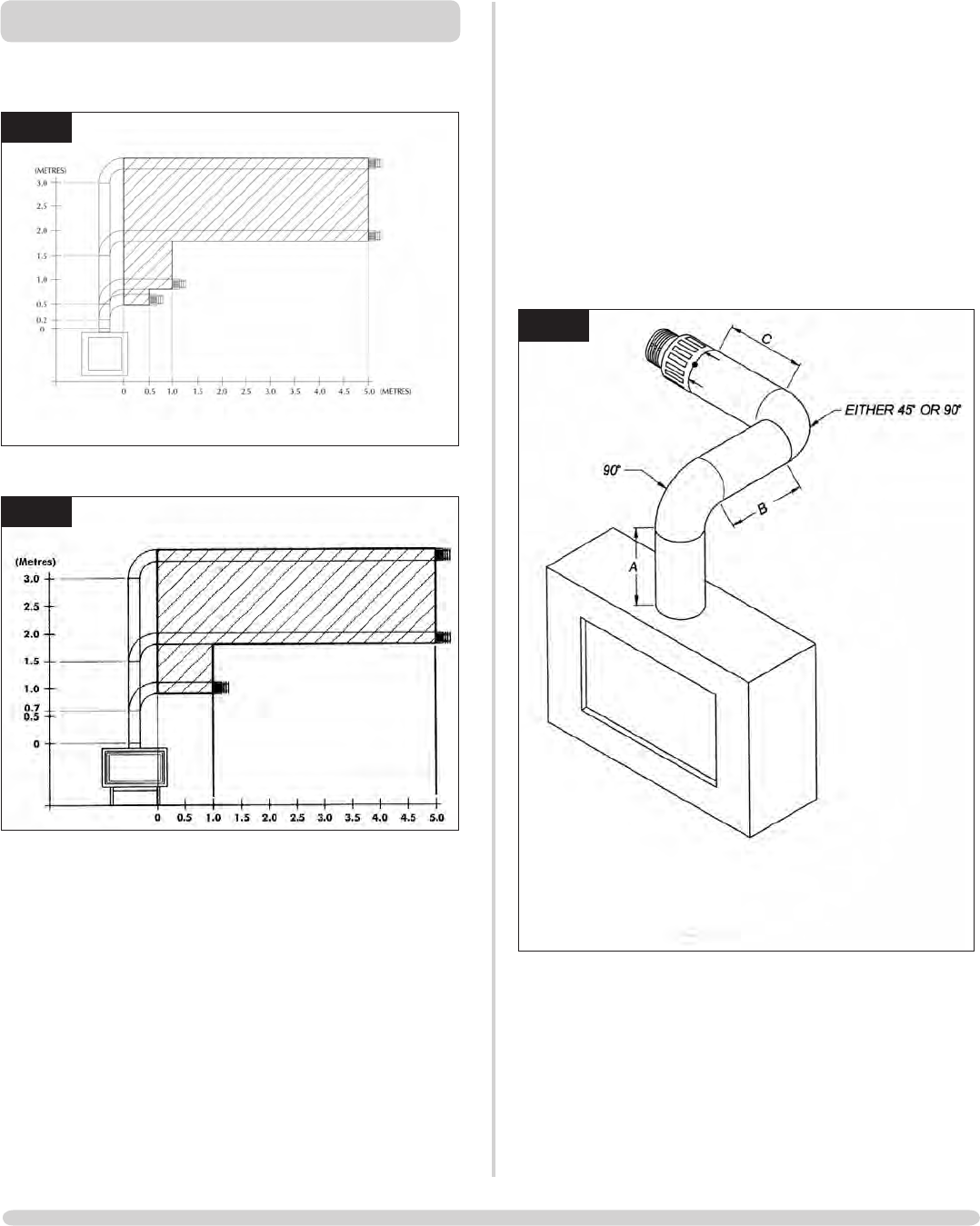
1B
AR1672
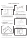
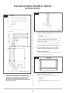
WhenA=1.0to1.499metesB&C=1.0metres
maximum
WhenA=1.499metresto3.0metresB&C=4.0
metres maximum
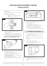
2.2 TOP FLUE UP & OUT WITH ADDITIONAL
BEND
Any additional bend may be used on the horizontal section
(either 45° or 90°), but the overall horizontal flue run will
be reduced. Refer to Diagram 1B.
2. FLUE OPTIONS