


12
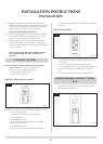
IMPORTANT: BEFORE THE APPLIANCE CAN BE
OPERATED THE REMOTE HANDSET MUST BE TUNED TO
THECONTROLBOXSITUATEDUNDERTHEAPPLIANCE.
IF THIS PROCEDURE IS OMITTED THE APPLIANCE CAN
ONLY BE LIT USING THE TOUCH PAD, SEE USER
INSTRUCTIONS, 2B TOUCH PAD CONTROL.
ENSURE THAT THE APPLIANCE IS CORRECTLY ADJUSTED
FOR THE GAS TYPE AND CATEGORY APPLICABLE IN THE
COUNTRY OF USE. REFER TO DATA BADGE AND THE
TECHNICAL SPECIFICATIONS ON PAGE 8.
FOR DETAILS OF CHANGING BETWEEN GAS TYPES REFER
TO THE SERVICING INSTRUCTIONS.
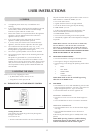
1. SAFETY PRECAUTIONS
1.1 This appliance must be installed in accordance with the
rules in force, and used only in a sufficiently ventilated
space. Please read these instructions before installation and
use of this appliance.
1.2 These instructions must be left intact with the user.
1.3 Do not attempt to burn rubbish on this appliance.
1.4 In your own interest, and those of safety, this appliance
must be installed by competent persons in accordance with
local and national codes of practice. Failure to install the
appliance correctly could lead to prosecution.
1.5 Keepallplasticbagsawayfromyoungchildren.
2. INSTALLATION OF THE APPLIANCE
2.1 Remove the appliance from the box and remove the two
screws, one from either side near the top of the black
surround.Thiswillreleasethewall-fixingbracket.
2.2
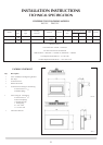
Decide on the position of the Linea and Decorative front and
mark the intended position of the outer bottom edge of the
frame. Refer to diagram 4 and 5 in the site requirements for
overall dimensions of the decorative frames.
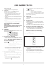
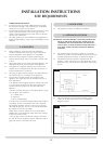
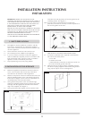
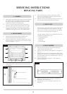
2.3 Having marked the position of the outer bottom edge,
position the template supplied ensuring that the line on the
wall aligns with the appropriate decorative frame bottom
edge on the template. See diagram 1.
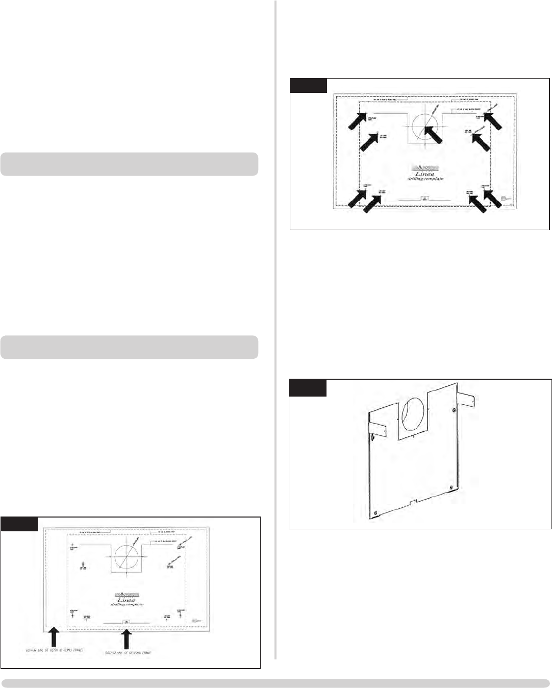
2.4 Having ensured that the template is level, mark the centre
of the flue hole and the position of four fixing holes for the
wall-fixingbracket.Seediagram2.
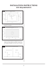
Note: If a Vetro, Plano or Steel decorative front has been
purchased, it will also be necessary to mark the positions of
the four fixing holes for the front.
TAKECAREWHENMARKINGOUTTHEFLUEASITIS
VERY DIFFICULT TO MOVE AFTER INSTALLATION.
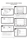
2.5 A 152mm (6") diameter hole is required to install the flue.
This can be achieved by either:
a) Core drill
b) Hammer and chisel
c) Drill small holes around the circumference, knock out
the centre and make good at both ends.
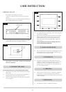
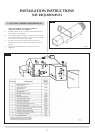
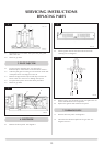
2.6 Whentheholeforthefluehasbeencompleted,insertthe
four brown rawplugs supplied and attach the fixing bracket
using only the top two screws. See diagram 2a.
INSTALLATION INSTRUCTIONS
INSTALLATION
1
AR1332
2
AR1347
2a
AR1418