


www.fmiproducts.com
125160-01A 7
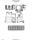
PRE-INSTALLATION PREPARATION
WARNING: Do not pack required air spaces
with insulation or other materials.
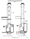
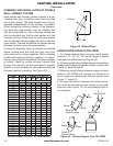
Minimum/Maximum Chimney Height for
Residential Installation
Minimum height of chimney, measured from base of
replace to ue gas outlet of termination, is 14 feet
for straight ue or 17 feet for a ue with one elbow
set. Maximum distance between elbows is 6 feet. For
systems with two elbow sets, minimum height is 22
feet. Maximum height of any system is 40 feet. This
measurement includes replace, chimney sections
and height of termination assembly at level of the
ue gas outlet (see Figure 20, page 16).
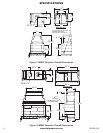
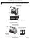
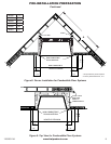
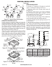
FRAMING
1. Frame opening for replace using dimensions shown
in Figures 6 and 7.
2. If replace is to be installed directly on carpeting,
tile (other than ceramic) or any combustible material
other than wood ooring, replace must be installed
upon a metal extending full width and depth of re-
place.
3. Set replace directly in front of this opening and
slide unit back until nailing anges touch side fram-
ing.
4. Check level of the replace and shim with sheet
metal if necessary.
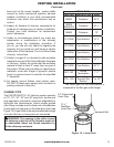
5. Before securing replace to prepared framing,
ember protector (provided) must be placed between
hearth extension (not supplied) and under bottom
front edge of replace to protect against glowing em-
bers falling through. If replace is to be installed on
a raised platform, a Z-type ember protector (not sup-
plied) must be fabricated to t your required platform
height. Ember protector should extend under replace
a minimum of 1
1
/
2
". Ember protector should be made
of galvanized sheet metal (26 gauge minimum to pre-
vent corrosion.
6. Using screws or nails, secure replace to framing
through anges located on sides of replace.
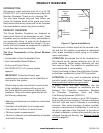
SELECTING LOCATION
To determine the safest and most efcient location
for the replace, you must take into consideration the
following guidelines:
1. The location must allow for proper clearances (see
Figures 6 and 7).
2. Consider a location where replace will not be af-
fected by drafts, air conditioning ducts, windows or
doors.
3. A location that avoids cutting of joists or roof raf-
ters will make installation easier.
4. An outside air kit is available with this replace
(see Optional Outside Air Kit on page 12).
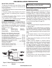
MINIMUM CLEARANCE TO COMBUSTIBLES
The distance to be maintained from the surfaces
of the replace to combustibles must be observed.
Below is a list of the most common combustible
materials to name a few:
Drywall Wood Flooring Plywood
Sub-Flooring Wood Framing Mill Board
Particle Board Plywood Paneling
Maintain the following clearances:
Unit sides, rear, Dome sides, rear & top..........2" min.
Combustible Floors (MM33,39,44,49)..............6" min.
Combustible Floors (MM63 only).....................8" min.
Combustible Sheathing above opening top..18" min.
Sheathing or trim to opening sides...................8" min.
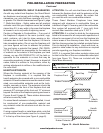
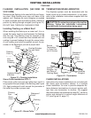
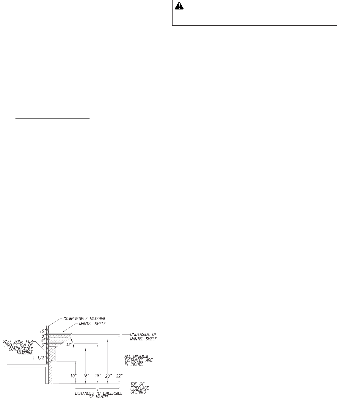
Mantel above opening..........................see Figure 5
Opening to sidewall...............................................24"
Hearth extension beyond front.............................20"
Hearth extension beyond sides............................12"
Insulation from rebox............................................2"
Figure 5: Mantel Clearances to Combustible
Material