


www.fmiproducts.com
125160-01A 15
VENTING INSTALLATION
Continued
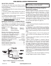
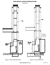
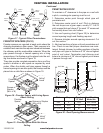
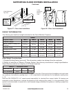
Figure 17 - Typical Offset Terminations
Return
Elbow
Elbow
Return
Elbow
Elbow
6' Max.
6' Max.
A
6' Max.
6' Max.
Return
Elbow
Elbow
Elbow
Return
Elbow
B
6' Max.
6' Max.
C
Elbow
Return
Elbow
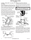
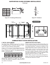
Ceiling Support
Pipe 12S-12DM
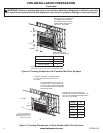
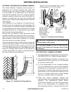
Figure 18 - Firestop Spacer with Living Space
Above Ceiling
FIRESTOP SPACERS (FS-10)
Firestop spacers are required at each point where the
chimney penetrates a oor space. Their purpose is to
establish and maintain the required clearance between
the chimney and the combustible materials. When the
pipe passes through a framed opening into a living
space above, the restop must be placed onto the ceil-
ing from below as shown in Figure 18.
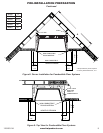
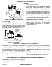
They also provide complete separation from one oor
space to another or attic space as required by most
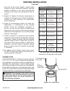
codes. When the double wall pipe passes through a
framed opening into an attic space, the restop must be
placed into an attic oor as shown in Figure 19.
Figure 19 - Firestop Spacer with Attic Above
Ceiling
Screws or
Staples
(Min. of 8)
Firestop
Spacer
Existing
Ceiling
Frame
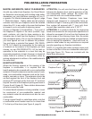
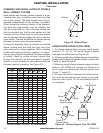
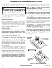
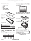
PENETRATING ROOF
To maintain a 2" clearance to the pipe on a roof with
a pitch, a rectangular opening must be cut.
1. Determine center point through which pipe will
penetrate roof.
2. Determine center point of roof. Pitch is distance
the roof drops over a given span, usually 12". A 6/12
pitch means that roof drops 6" for each 12" measured
horizontally down from roof rafters.
3. Use roof opening chart (Figure 20) to determine
correct opening length and ashing required.
4. Remove shingles around opening measured. Cut
out this section.
5. Add next sections of pipe until end penetrates roof
line. Check to see that proper clearances are main-
tained. Extend chimney by adding sections of double
wall pipe until pipe is minimum of 30” above highest
point of roof cutout. Termination and chimney must
extend a minimum of 36” above highest point where
it passes through roof.
Existing
Ceiling
Frame
Screws or Staples
(Min. of 8)
Firestop
Spacer
Pitch Slope Opening
"A" Max.
Used Flashing
Model No.
Flat 0° 19.5" V6F-10DM
0-6/12 26.6° 22' V6F-10DM
6/12-12/12 45.0° 27" V12F-10DM
19.5" Min.
30" Min.
2" Min.
2" Min.
2" Min.
Opening "A"
Figure 20 - Roof Opening Measurements